



Car transmission line Skoda Superb 2

Transmission Line Specifications
Types and volumes of fluids - see Specifications for Chapter 1 Diameter of flanges of rear drive shafts (rear final drive 0BR), mm - 100 Front drive shaft flange diameter, mm Manual transmission 0A4, 0AJ - 100 RKPP 02Q...
Types and volumes of fluids - see Specifications for Chapter 1 Diameter of flanges of rear drive shafts (rear final drive 0BR), mm - 100 Front drive shaft flange diameter, mm Manual transmission 0A4, 0AJ - 100 RKPP 02Q...

General information about the transmission line
Attention: Do not allow excessive stress and damage to the anthers of the CV joints of the drive shafts; do not bend the shaft to the stop; do not allow the drive shafts to fall, as this can damage the inside of the CV...
Attention: Do not allow excessive stress and damage to the anthers of the CV joints of the drive shafts; do not bend the shaft to the stop; do not allow the drive shafts to fall, as this can damage the inside of the CV...

Replacing the hub assembly of the front wheel, turning out and tightening the hub bolt
1. The front wheel hubs, together with the wheel bearings, form a single non-separable unit, mounted on the steering knuckles. Details of the installation of the steering knuckle and the hub assembly of the front wheel...
1. The front wheel hubs, together with the wheel bearings, form a single non-separable unit, mounted on the steering knuckles. Details of the installation of the steering knuckle and the hub assembly of the front wheel...
Removal and installation of the rear hub assembly and its holder
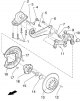
1. The installation details of the rear hub assembly are shown on Ref. illustrations. The hub and the wheel bearing are combined into a non-separable maintenance-free assembly, fixed on the holder. 3.1a Installation...
1. The installation details of the rear hub assembly are shown on Ref. illustrations. The hub and the wheel bearing are combined into a non-separable maintenance-free assembly, fixed on the holder. 3.1a Installation...

Removal and installation of power shafts
Note: Depending on the installed transmission, one of five front drive shaft options can be installed: "VL100", "VL107", "AAR3300i", "RO104" or "R03700". Illustrations explaining the differences between the front drive...
Note: Depending on the installed transmission, one of five front drive shaft options can be installed: "VL100", "VL107", "AAR3300i", "RO104" or "R03700". Illustrations explaining the differences between the front drive...

Drive shaft repair
1. Details of the drive shaft assemblies are indicated on the resist. illustrations. 5.1a Installation details of the front drive shaft "VL100" 1 Outer CV joint, replaceable as an assembly 2 Hub bolt, to be replaced, 70...
1. Details of the drive shaft assemblies are indicated on the resist. illustrations. 5.1a Installation details of the front drive shaft "VL100" 1 Outer CV joint, replaceable as an assembly 2 Hub bolt, to be replaced, 70...

Removal and installation of angular transmission
Models with DSG "02E" 1. Remove the right front wheel. 2. Remove the soundproofing under the engine compartment and the locker of the right front wheel arch. 3. Remove all exhaust system supports from transmission and...
Models with DSG "02E" 1. Remove the right front wheel. 2. Remove the soundproofing under the engine compartment and the locker of the right front wheel arch. 3. Remove all exhaust system supports from transmission and...

Removal and installation of cardan shaft
1. Details of the installation of the cardan shaft are indicated on the resist. illustrations. 7.1 PTO shaft installation details 1 corner drive 2 Bolts M 10x30, 3 pcs., 60 Nm 3 Cardan shaft, during installation,...
1. Details of the installation of the cardan shaft are indicated on the resist. illustrations. 7.1 PTO shaft installation details 1 corner drive 2 Bolts M 10x30, 3 pcs., 60 Nm 3 Cardan shaft, during installation,...

Removal and installation of the block «J492» all-wheel drive control
1. Block assembly details "J492" all-wheel drive controls are indicated on the sopr. illustrations. Block "J492" and valve "N373" calibrated together and replaced also together. 9.1 Block assembly details "J492"...
1. Block assembly details "J492" all-wheel drive controls are indicated on the sopr. illustrations. Block "J492" and valve "N373" calibrated together and replaced also together. 9.1 Block assembly details "J492"...
Cardan shaft repair
1. The cardan shaft is balanced during manufacture. Because balancing in a repair shop is not possible; if the shaft fails, it must be completely replaced. 2. If parts of the cardan shaft are damaged, it will need to be...
1. The cardan shaft is balanced during manufacture. Because balancing in a repair shop is not possible; if the shaft fails, it must be completely replaced. 2. If parts of the cardan shaft are damaged, it will need to be...

Removal and installation of the pump «V181» Haldex couplings
1. Turn off the ignition. 2. Place a drip tray under the Haldex coupling. 3. Remove the filler plug ( And in illustration 4.41 d of Chapter 1 ), remove the drain plug (IN) and drain the Haldex coupling fluid. Tighten a...
1. Turn off the ignition. 2. Place a drip tray under the Haldex coupling. 3. Remove the filler plug ( And in illustration 4.41 d of Chapter 1 ), remove the drain plug (IN) and drain the Haldex coupling fluid. Tighten a...

Removal and installation of the Haldex coupling
1. Installation details of the Haldex coupling are shown on the resist. illustrations. 11.1 Installation details of the Haldex coupling 1 O-ring between clutch and rear final drive, to be replaced 2 Haldex coupling...
1. Installation details of the Haldex coupling are shown on the resist. illustrations. 11.1 Installation details of the Haldex coupling 1 O-ring between clutch and rear final drive, to be replaced 2 Haldex coupling...

Removal and installation of the rear final drive with differential
1. Details of the installation of the rear final drive are indicated on resp. illustrations. 12.1 Installation details of the rear final drive Arrow Direction of movement 1 Rear subframe 2 drive shaft 3 Rear final drive...
1. Details of the installation of the rear final drive are indicated on resp. illustrations. 12.1 Installation details of the rear final drive Arrow Direction of movement 1 Rear subframe 2 drive shaft 3 Rear final drive...
This section is available on russian, bulgarian, belarusian, ukrainian, serbian, croatian, romanian, polish, slovak, hungarian
Link to this section in various formats
TEXTHTMLBB Code
- General information
- User manual
- Car driving
- Maintenance
- Power unit
- Petrol engines 3.6 l
- Petrol engines 1.4 l
- Petrol engines 1.8/2.0 l
- Diesel engines 2.0 l
- Diesel engines 1.9 l
- Cooling system
- Climate system
- Power and exhaust system
- Ignition and preheat system
- Launch and charge system
- Transmission
- Manual gearbox and clutch
- 7-speed DSG gearbox
- 6-speed DSG gearbox
- Transmission line
- Chassis (running gear)
- Brake system
- Front suspension
- Rear suspension
- Steering
- Body and interior
- Exterior (external elements)
- Interior (internal elements)
- Electrical equipment
- Equipment and devices
- Lighting and signaling