
Models with DSG "02E"
1. Remove the right front wheel.
2. Remove the soundproofing under the engine compartment and the locker of the right front wheel arch.
3. Remove all exhaust system supports from transmission and exhaust pipe. Separate the exhaust system on a double clamp and remove the exhaust system bracket from the subframe. Tie up the exhaust pipe without bending its flexible section more than 10°.
4. Disconnect the engine oil temperature and level sensor connector located on the underside of the engine oil pan.
5. If available, disconnect the connector of the left front suspension height sensor, give the nut (2 in Illustration 5.23 of Chapter 6), unscrew the bolt (1) and remove the sensor.
6. Fix the position of the subframe and remove it together with the swing arm, stabilizer, consoles, steering gear and front suspension arms (see chapter 10).
7. Remove the right drive shaft guard from the bevel gear (see illustration 30.11 of Chapter 2), remove the right drive shaft from the DSG flange shaft and hang the drive shaft on the right suspension strut with a suitable belt.
Note: Be careful not to damage the protective coating of the drive shaft.
9. Mark the position of the cardan shaft with a flexible disk relative to the output flange of the angular transmission and fasten the cardan shaft to the output flange (see illustration 5.19 Chapter 6).
10. Press the power unit forward and pull the cardan shaft off the output flange of the angular gear.
Note: After removing the oscillating arm from the DSG, the power unit tilts forward slightly, so be careful not to damage the gasket (see resist. illustration) in the driveshaft flange.
Raise and tie up the propeller shaft so that it does not hang down.
11. On diesel models with a particulate filter, remove it together with the bracket (see chapter 4) and remove the bolt (see illustration 6.11a) fastening the right flanged DSG shaft using the T10107A head. At the same time, to prevent the shaft from turning, screw two bolts into the flange, insert a metal bar between them and hold the flange by it. Remove the right flange shaft (see illustration 6.11b) collecting escaping DSG fluid (on models without diesel particulate filter, the right flanged shaft remains in the DSG).
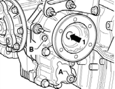
6.11a Bolt (1) right flange shaft
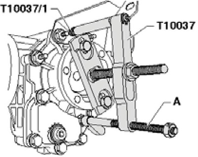
6.11b Removing the right flange shaft
12. Remove the support from the turbocharger (And in illustration 5.27 of Chapter 6 or in illustration 15.27 of Chapter 7), remove the hollow bolt (IN) and remove the support. Remove the bolts (1-3) DSG mounts on the engine and on the corner gear. When using the support indicated on Figure 15.27 Chapter 7, bolt (3) cannot be turned out completely, because it rests on the right flange shaft (IN), and the support can only be removed after the DSG has been removed from the engine.
13. On 3.6 l models, remove the bolts (see resist. illustration) attaching the DSG mount to the engine and to the DSG and remove the mount.
6.13 Fixing the DSG support on 3.6l models
14. Turn out bolts (see resist. illustration), carefully separate the bevel gear from the DSG and remove the bevel gear by sliding it down between the engine oil pan and subframe.
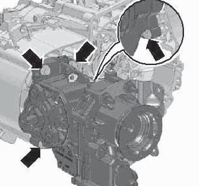
6.14 Corner drive bolts
15. Installation is carried out in the reverse order. Finally, check and, if necessary, correct the oil level in the DSG and bevel gear.
Models with manual transmission "02Q"
16. If there is a breather on the corner gear (see illustration 5.7 Chapter 6), remove it, having previously removed the gearshift mechanism from the manual transmission (see chapter 6).
17. Jack up the car and place it on secure stands. Remove the front wheels.
18. Remove the sound insulation under the engine compartment (see chapter 11).
19. Follow the steps described in paragraphs 3-6 and 9-10.
20. If available, remove the protective cover from the corner drive (And in illustration 4.40 of Chapter 1) right drive shaft by unscrewing the bolts (1). On models with auxiliary heater, remove from bevel gear and engine (2) coolant pipes (IN), without opening the cooling circuit. Remove the right drive shaft from the DSG flange shaft and hang the drive shaft on the right suspension strut with a suitable belt.
Note: Be careful not to damage the protective coating of the drive shaft.
21. Remove the bolt (see illustration 6.11a) fixing the right flange shaft DSG. using the T10107A head. At the same time, to prevent the shaft from turning, screw two bolts into the flange, insert a metal bar between them and hold the flange by it.
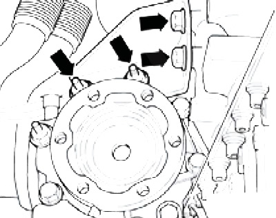
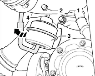
22. On models without a particulate filter, remove the oil line from the engine (And in illustration 5.26 of Chapter 6) turbocharger, remove the bolts (arrows) manual transmission supports on the engine and on the corner gear and remove the support. If necessary, turn the boost pressure regulator slightly to gain access to the upper bevel gear bolts on the manual transmission (3 on resist. illustrations) in the direction of the arrow. To do this, unscrew the bolt (1) and loosen the bolt (2). Don't damage the traction (4).
6.22 Access to the top bolts
23. On diesel models with a particulate filter, remove it together with the bracket and remove the right flange shaft (see illustration 6.11b), collecting the escaping DSG fluid (on models without a diesel particulate filter, the right flange shaft remains in the manual transmission). Then remove the support from the turbocharger (And in illustration 5.27 of Chapter 6), remove the hollow bolt (IN) and remove the support. Remove the bolts (1-3) manual transmission supports on the engine and on the corner gear.
24. Turn out the bottom bolts of fastening of manual transmission to the engine (see resist. illustration).
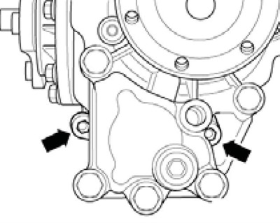
6.24 Lower bolts for fastening the corner gear to the manual transmission
25. Some models have a heat shield on the top side of the corner drive (And on the opposite illustrations). Remove the bolt (IN) bottom and bolt (WITH) from above, and then carefully separate the corner gear from the manual transmission.
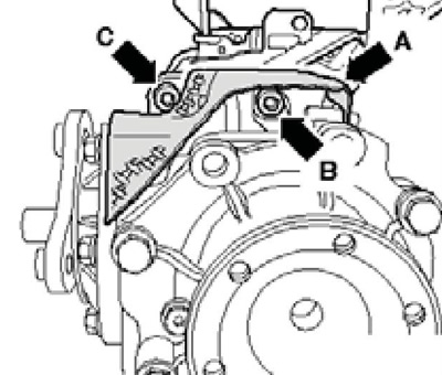
6.25 Angle drive fastener
26. If a new bevel gear is to be installed, move the heat shield to it (see resist. illustration).
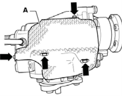
6.26 Mounting the heat shield on the corner drive
27. Lubricate the differential splines with G000 100 clutch spline grease. Fit the bevel gear and slide it onto the DSG as far as it will go. If the splines do not match, rotate the flanged shaft. Only when the bevel gear is pressed against the DSG, tighten the new bevel gear bolts diagonally.
28. Further installation is carried out in reverse order. Finally, check and, if necessary, correct the oil level in the bevel gear and manual transmission.