



Diesel engines TDI-CR 2.0L Generation II Skoda Superb 2

Diesel Engine Specifications 2.0
Diesel engines 2.0 l 103 kW TDI-PD Type - Diesel, 4-cylinder, in-line, SOHC (BMP code) or DOHC (BKD code), turbocharged Designations - BMP, BKD The order of operation of the cylinders is 1-3-4-2 Cylinder diameter //...
Diesel engines 2.0 l 103 kW TDI-PD Type - Diesel, 4-cylinder, in-line, SOHC (BMP code) or DOHC (BKD code), turbocharged Designations - BMP, BKD The order of operation of the cylinders is 1-3-4-2 Cylinder diameter //...

Removal and installation of the engine and support of the power unit
Removal and installation Note: The engine is removed from under the engine compartment down along with the transmission. 1. Remove the engine top cover. To do this, sequentially pull it out of the supporting hinge...
Removal and installation Note: The engine is removed from under the engine compartment down along with the transmission. 1. Remove the engine top cover. To do this, sequentially pull it out of the supporting hinge...

Removal and installation of the accessory drive belt, its tensioner, auxiliary bracket and crankshaft pulley
1. Details of the installation of the drive of auxiliary units are indicated on Ref. illustrations. 35.1 Accessories drive parts (on the example of models with a compressor) 1 crankshaft pulley 2 Bolt, 25 Nm 3 Generator...
1. Details of the installation of the drive of auxiliary units are indicated on Ref. illustrations. 35.1 Accessories drive parts (on the example of models with a compressor) 1 crankshaft pulley 2 Bolt, 25 Nm 3 Generator...

Removal and installation of the timing belt, installation of timing phases
1. Details of the installation of the timing belt and engine bracket are indicated on the resp. illustrations. 36.1 Timing belt installation details 1 timing belt 2 Gear bolt 3, to be replaced, 120 Nm, then tighten 90°...
1. Details of the installation of the timing belt and engine bracket are indicated on the resp. illustrations. 36.1 Timing belt installation details 1 timing belt 2 Gear bolt 3, to be replaced, 120 Nm, then tighten 90°...

Removal and installation of some parts related to the crankshaft
1. Installation details of the crankshaft oil seals, their sealing flanges and some related components are indicated on Ref. illustrations. 37.1a Installation details of crankshaft oil seals, their sealing flanges and...
1. Installation details of the crankshaft oil seals, their sealing flanges and some related components are indicated on Ref. illustrations. 37.1a Installation details of crankshaft oil seals, their sealing flanges and...

Removal and installation of a cover of a head of cylinders
1. Details of installation of a cover of a head of cylinders are specified on sopr. illustrations. 38.1 Installation details of the cylinder head cover 1 Gasket 2 Cylinder head cover 3, 14, 16 O-ring, to be replaced 4...
1. Details of installation of a cover of a head of cylinders are specified on sopr. illustrations. 38.1 Installation details of the cylinder head cover 1 Gasket 2 Cylinder head cover 3, 14, 16 O-ring, to be replaced 4...

Removal and installation of the cylinder head, vacuum pump and CMP sensor
Note: When removing the cylinder head, the temperature of the engine must not exceed 35°C, otherwise the cylinder head may be deformed after loosening its bolts. 1. Installation details of the cylinder head, vacuum pump...
Note: When removing the cylinder head, the temperature of the engine must not exceed 35°C, otherwise the cylinder head may be deformed after loosening its bolts. 1. Installation details of the cylinder head, vacuum pump...
Work with the gas distribution mechanism
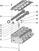
1. The design of the timing is shown in resist. illustrations. 40.1 Timing parts 1 valve 2 Cylinder head 3 Oil cap 4 Valve spring 5 Spring plate 4 6 Split valve lock crackers 7 Cover, to be replaced 8 Oil seal 9 Exhaust...
1. The design of the timing is shown in resist. illustrations. 40.1 Timing parts 1 valve 2 Cylinder head 3 Oil cap 4 Valve spring 5 Spring plate 4 6 Split valve lock crackers 7 Cover, to be replaced 8 Oil seal 9 Exhaust...

Work with the lubrication system and balancer shafts
1. Details of the installation of the oil pan and oil pump are indicated on Ref. illustrations. 41.1 Installation details of the oil pan, oil pump and balancer shaft module 1 O-ring, cannot be separated from the plug 2...
1. Details of the installation of the oil pan and oil pump are indicated on Ref. illustrations. 41.1 Installation details of the oil pan, oil pump and balancer shaft module 1 O-ring, cannot be separated from the plug 2...

Engine overhaul features
Note: The presence of metal chips or a large number of small metal particles found during engine repairs may indicate damage to the crankshaft bearings and connecting rods. To prevent further damage from developing,...
Note: The presence of metal chips or a large number of small metal particles found during engine repairs may indicate damage to the crankshaft bearings and connecting rods. To prevent further damage from developing,...
This section is available on russian, bulgarian, belarusian, ukrainian, serbian, croatian, romanian, polish, slovak, hungarian
Read similar sections on other Skoda models
➧ Power unit: Diesel engines Skoda Rapid 1 (2012-2022)
➧ Power unit: Diesel engine Skoda Felicia (1994-2001)
Link to this section in various formats
TEXTHTMLBB Code
- General information
- User manual
- Car driving
- Maintenance
- Power unit
- Petrol engines 3.6 l
- Petrol engines 1.4 l
- Petrol engines 1.8/2.0 l
- Diesel engines 2.0 l
- Diesel engines 1.9 l
- Cooling system
- Climate system
- Power and exhaust system
- Ignition and preheat system
- Launch and charge system
- Transmission
- Manual gearbox and clutch
- 7-speed DSG gearbox
- 6-speed DSG gearbox
- Transmission line
- Chassis (running gear)
- Brake system
- Front suspension
- Rear suspension
- Steering
- Body and interior
- Exterior (external elements)
- Interior (internal elements)
- Electrical equipment
- Equipment and devices
- Lighting and signaling