



Caution: Avoid excessive stress and damage to the CV joint boots of the drive shafts; do not bend the shaft all the way; do not allow the drive shafts to fall, as this may result in damage to the inside of the CV joint boots without any external signs of this occurring.
The cars in question, depending on the version, have either a front-wheel drive or a front-wheel drive only (fWD models), or on all wheels (aWD models). On FWD models, torque is transmitted to the front wheels via drive shafts from the manual transmission/DSG differential (see illustrations 1.2ab,d Chapter 6).
The variable angle of inclination of the drive shafts is achieved by means of constant velocity joints (CV joints) placed in protective corrugated boots. The outer CV joints are attached to the wheel hubs. The drive shafts have the same length, so an intermediate shaft is installed between the right drive shaft and the transmission of FWD models, secured on the drive shaft side in an intermediate support.
Organization of all-wheel drive
On AWD models, the right-hand side of the front differential is fitted with an angular transmission that provides power take-off for the rear wheels. The rear wheels are driven from the angular transmission via a propeller shaft, a 4th-generation Haldex clutch, a rear final drive with differential and rear drive shafts (see illustration 1.2c Chapter 6).
The Haldex coupling is integrated into the rear final drive and can be replaced separately. The oil supply to the Haldex coupling and final drive is carried out via two separate oil circuits. Two types of oil that meet the respective requirements are used for lubrication and cooling. Mixing or mixing these oils leads to severe damage to the Haldex coupling or final drive.
The procedure for checking and adjusting the angular gear, Haldex clutch and final drive fluid levels is described in Section 4 of Chapter 1. The Haldex clutch fluid should be replaced in accordance with the maintenance schedule (see Sections 3 and 22 Chapters 1).
The main advantages include:
- control of pump flow depending on demand;
- clutch control depending on driving style;
- acceleration of torque build-up due to advanced control;
- compatible with ABS and ESP systems;
- independence from traffic conditions.
The identification data for the rear final drive is indicated on its housing (see illustration 1.1).
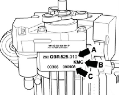
1.1 Part number (A, "0BR"), code (B, "KMS") and production date (C, "090908") of the rear final drive
Distribution of traction force between axles using the Haldex clutch is carried out in multiple variants, depending on the driving parameters (traction, load, economy, dynamics, forced idle mode, maneuvering). The following components are involved in the electronic control of the all-wheel drive:
- engine control unit "J623" (crankshaft speed, torque and power signals);
- instrument cluster control unit (wheel circumference signal);
- ABS/ESP control unit "L04" (brake and wheel speed signals);
- steering wheel angle sensor;
- all-wheel drive control unit "J492" (torque definition).
Features of carrying out repair work on the rear main gear
1. When installing support brackets or waxed components, clean mating surfaces of wax and grease.
2. Thoroughly clean the separating surfaces and apply AMV 188 200 03 sealant to them.
3. Apply sealants evenly and not in too thick a layer.
Information published on the website: skodabook.ru
4. Before installing the radial seals (oil seals), fill the space between the sealing lips halfway with G052 128 A1 grease (see illustration 2.4 Chapter 6).
5. The open side of the seal must face the working fluid.
6. Lightly lubricate the sealing rings before installation to avoid damaging them during installation.
7. After replacing the seal, check and adjust the working fluid level (see Chapter 1).
8. Loosen and tighten the threaded fasteners of the covers and housings in a diagonal order.
9. The tightening forces indicated apply to unlubricated threaded fasteners.
10. Replace self-locking nuts and bolts.
11. Remove any remaining thread locking compound from the threaded holes using a taper before screwing in the self-locking bolts. Otherwise, there is a risk of the bolts being sheared off when they are subsequently unscrewed.
12. Install new tapered roller bearings as supplied; do not apply additional lubricant.
13. Install the needle bearings so that the side with the letters (thicker layer of metal) was turned towards the installation device.
14. Tapered roller bearings mounted on one shaft must be replaced as an assembly.
15. Before installation, heat the inner bearing races to approximately 100°C.
16. Do not interchange the outer and inner races of bearings of the same size, as they are matched in pairs.