



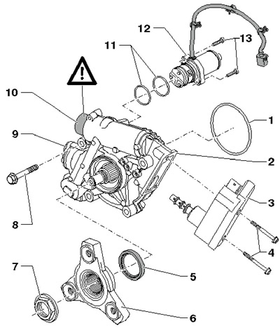
11.1 Haldex coupling installation details
1 O-ring between the clutch and the rear final drive, subject to replacement
2 Haldex coupling housing
3 Block "J492" of all-wheel drive control
4 Bolts, 6 Nm
5 Flange seal 6
6 Cardan shaft flange
7 Nut, 210 Nm, subject to replacement, installed with fixing sealant D000 600
8 Bolts for fastening coupling 2 to the rear main gear, 4 pcs., 50 Nm
9 Filter housing cover
10 Pressure accumulator cover
11 Pump sealing rings 12, diameter 34 mm, subject to replacement
12 Pump "V181" Haldex couplings Bolts, 6 Nm
2. Jack up the car and place it on reliable supports.
3. Disconnect the exhaust system at the double clamp and remove the exhaust system bracket from the subframe. Tie up the exhaust pipe, preventing its flexible section from bending more than 10°. Remove the rear part of the exhaust system from the double clamp.
4. Remove the heat shield under the propeller shaft and unscrew the bolts (see illustration 7.11) its intermediate bearing by approximately 4 turns.
5. Remove the rocker support from the transmission by unscrewing the bolts (B and C in Illustration 5.20 Chapter 6).
6. Check that there are color marks on the flexible disk of the cardan shaft and on the flange of the Haldex coupling (see illustration 7.9). Apply these marks if necessary.
7. Remove the bolts securing the propeller shaft to the Haldex coupling flange (see illustration 7.10).
8. Together with an assistant, push the power unit forward (arrow on the accompanying illustration) and insert a suitable wooden block (A) approximately 50 mm thick between the subframe (B) and the transmission (C). At the same time, remove the propeller shaft from the centering pin of the Haldex coupling flange in a horizontal direction so as not to damage the gaskets (see illustration 5.21 Chapter 6) in the flanges of the cardan shaft.
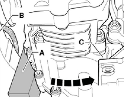
11.8 Installing a block between the transmission and the subframe
9. Tie up the driveshaft (And on the accompanying illustration) on the suspension (B) of the exhaust system.
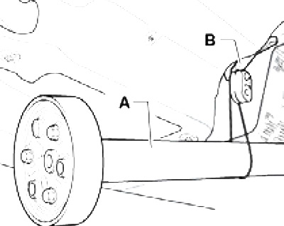
11.9 Fixing the cardan shaft
10. Disconnect the connector (2 in illustration 9.3).
11. Place a drip tray under the Haldex coupling to collect the fluid.
12. Unscrew the filler plug (And in illustration 4.41 d Chapter 1), unscrew the drain plug (B) and drain the Haldex coupling fluid. Tighten the new plug with a new seal to 30 Nm.
13. Remove the bolts (see accompanying illustration) and remove the Haldex clutch from the rear final drive.
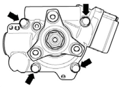
11.13 Haldex coupling mounting bolts
14. Replace the sealing ring (see accompanying illustration). When installing, lubricate it with Haldex coupling fluid.
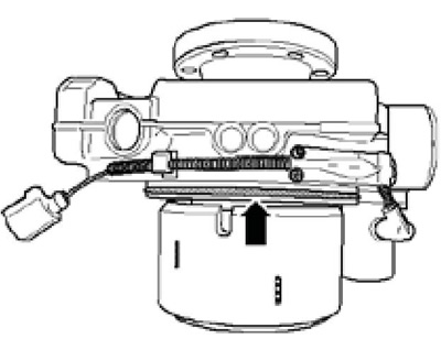
11.14 Sealing ring
15. Installation is carried out in the reverse order. When connecting the coupling to the rear main gear, you can use guide pins; if necessary, rotate the coupling flange to align it with the rear final drive. Tighten the Haldex coupling mounting bolts to 50 Nm.
16. Finally, fill the Haldex coupling with working fluid (see Section 4 Chapter 1).