



Contents: Removal and installation the…⬇ Capacitor ⬇ Replacing the desiccant cartridge…⬇ Replacing the dehydrator cartridge…⬇ Evaporator ⬇
Note: The location of the refrigeration unit components is shown in Figure 8.2. A description of replacing the evaporator temperature sensor "G263" is given in Section 14.
Note: On models with a Denso condenser, the receiver and dryer are part of the condenser and cannot be replaced separately. On models with Showa and Fujikoki parts, the receiver is replaced together with the desiccant cartridge. On models with "Modine" parts, the receiver is part of the condenser, and the dehydrator can be replaced separately from them. The receiver-dryer needs to be replaced only after: the compressor has seized up, the refrigerant circuit has been open for an indefinite period of time (for example, with long-term coloring) or the coolant circuit was bled.
1. If there is a lid (3 in the illustration) expansion valve to remove it, disconnect the coolant lines from the heater radiator, loosen the nut (1) and remove the clamps (2). When installing, tighten the nut with a force of 6 Nm.
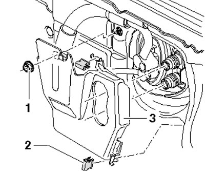
18.1. Expansion valve installation details
Removal and installation the expansion valve
2. On some engines, it may be necessary to remove the top engine cover to gain easier access to the expansion valve (see chapter 2), turbocharger inlet hose, particulate filter cover and air cleaner inlet hose (see Chapter 4).
3. Drain the refrigerant.
4. If present, remove the expansion valve cap (see paragraph 1).
5. Remove the bolts (1 in the illustration) and separate the refrigerant lines from the expansion valve (2).
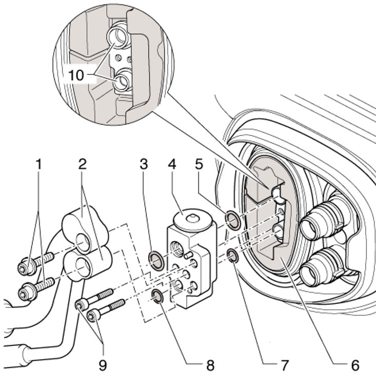
18.5. Expansion valve installation details 1. Bolts, 12 Nm; 2. Refrigerant lines at the expansion valve; 3, 5, 7, 8. Sealing ring; 4. Expansion valve; 6. Thermal insulation; 9. Bolts, 5 Nm; 10. Evaporator connections
Remove the bolts (9) and remove the expansion valve from the thermal insulation (6). Use new refrigerant line sealing rings when installing.
Capacitor
6. Drain the refrigerant from the refrigeration unit.
7. Remove the hood lock holder (see Chapter 11).
8. Disconnect the refrigerant lines from the condenser (see illustration 8.2) and seal them.
9. Unscrew 4 bolts and remove the condenser from the radiator (1 in the illustration).
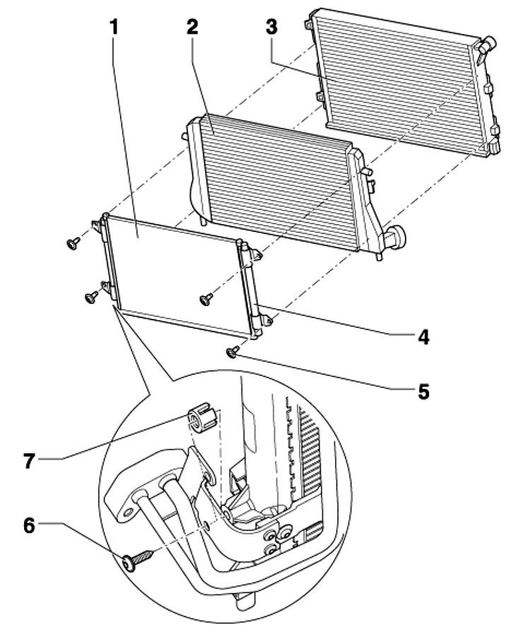
18.9. Details of the installation of the condenser and receiver-dryer 1. Capacitor; 2. Intercooler; 3. Radiator; 4. Receiver-dryer; 5. Bolts, 4 pcs., 5 Nm; 6. Bolt, 5 Nm; 7. Support, on some models
10. Installation is carried out in reverse order.
Replacing the desiccant cartridge ("Showa" and "Fujikoki")
11. Drain the refrigerant from the refrigeration unit.
12. Remove the hood lock holder (see Chapter 11).
13. Without disconnecting the coolant hoses, secure the condenser with wire.
14. Unscrew the bolt (1 in the illustration) and remove the clamp (2). Then unscrew the bolts (5) and pull the receiver with the dryer (3) upward.
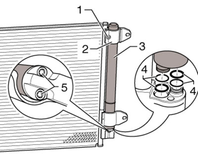
18.14. Replacing the desiccant cartridge ("Showa" and "Fujikoki")
15. Installation is carried out in reverse order. Use new o-rings (1 in illustration 18.14). First tighten the bolts (5) and then the bolt (1) to 5 Nm.
Replacing the dehydrator cartridge (condenser "Modine")
Note: It is not necessary to replace the cartridge every time the refrigerant circuit is depressurized for a short time if the vehicle is less than 5 years old.
16. Remove the front bumper cover (see Chapter 11).
17. Remove the plug (1 in the illustration) and drain the refrigerant from the refrigeration unit.
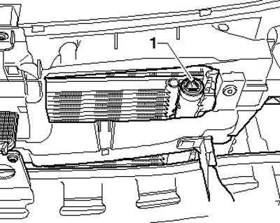
18.17. Cartridge plug
18. Press the sealing cap (1 in the illustration) into the receiver, remove the retaining ring (arrow) and pull the sealing cover out of the condenser (2) using the M12 bolt.
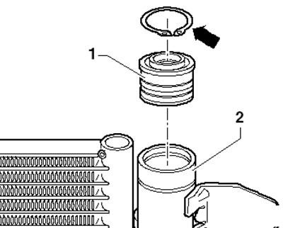
18.18. Sealing cover (1)
19. Remove the desiccant bag from the condenser using a suitable tool (see illustration).
Source of the article web resource: SKODABOOK.ru
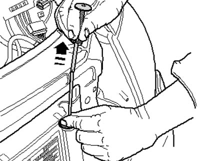
18.19. Removing the desiccant bag
20. Bend the end of a 2mm welding electrode 380mm long into a hook with a diameter of 6mm (1 in the illustration) and remove the cartridge (2) from the condenser.
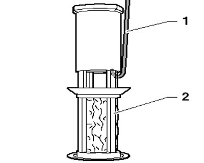
18.20. Removing the evaporator cartridge (2) using a curved electrode (1)
21. Insert the new cartridge into the condenser, and then insert the desiccant bag into the condenser.
22. Further installation is carried out in reverse order.
Evaporator
23. Remove the climate control system housing and disassemble it, removing the evaporator from its lower casing (see Section 15).
24. Before installing the evaporator, check the drainage hose for leaks and clean it if necessary.
25. Make sure the seal is (F in the illustration) worn around the entire perimeter. Place the holder (C) with the seal (B) on the connections (D and E) and insert the evaporator (A) into its lower casing as shown in the illustration. When doing this, and when installing the upper casing, be careful not to damage the seal (F). After connecting the casings, check that the casings are positioned correctly.
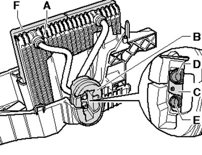
18.25. Evaporator seal details