



Contents: Petrol engines 1.2 and 1.4 l ⬇ Petrol engines 1.8 l ⬇ Diesel engines 2.0 l (CFHC, CFJA and…⬇
1. Description of replacement of the filter element is given in Section 16 Chapter 1. The following describes the procedure for removing the air cleaner assembly.
Petrol engines 1.2 and 1.4 l
Note: The description of removal/installation is given using a 1.2 l engine as an example.
2. The details of installation and assembly of the air cleaner are shown in the illustration.
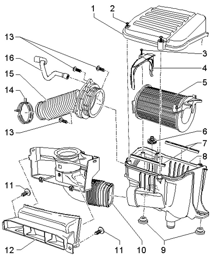
4.2. Installation and assembly details of the air cleaner for 1.2 and 1.4 l petrol engines 1. Air cleaner cover; 2, 3, 11, 13. Bolt, 2 Nm; 4. Holder; 5. Filter element; 6. Rubber-metal support with captive screw, 8 Nm; 7. Seals; 8. Air cleaner housing; 9. Rubber support; 10. Inlet connection, with cover; 12. Air intake; 14. Spring band clamp; 15. Air hose, to turbocharger; 16. Vacuum hose, to cylinder head cover
3. Press the clamps (arrows in the illustration) and remove the cover (1) from the inlet connection. Separate the inlet connection from the air intake, loosen the clamp (2) and remove the air hose from the turbocharger.
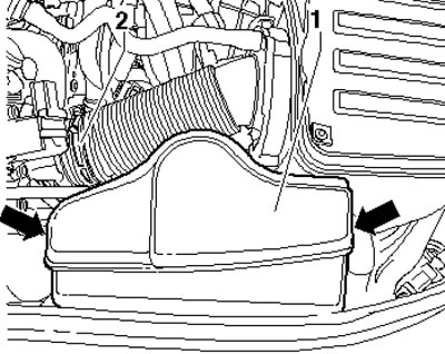
4.3 Air Cleaner Connections
4. Disconnect the vacuum hose from the air cleaner housing (1 in the illustration), unscrew the bolt (2) and remove the air cleaner from the supports (3) in an upward direction.
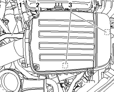
4.4. Vacuum hose and air cleaner fasteners
6. Installation is carried out in reverse order.
Petrol engines 1.8 l
7. The details of installation and assembly of the air cleaner are shown in the illustration.
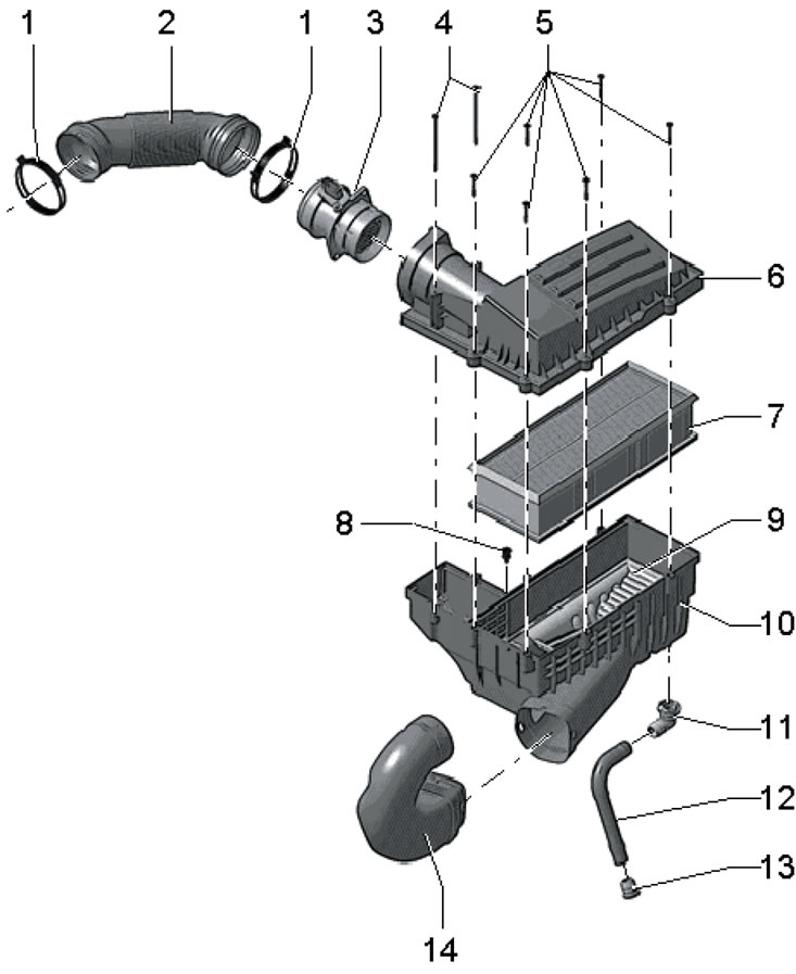
4.7. Installation and assembly details of the air cleaner for 1.8 l petrol engines 1. Spring clamp; 2. Inlet hose, to turbocharger; 3. Air flow sensor "G70" with IAT sensor No. 2 "G299"; 4, 5. Captive cover bolts 6, 1.5 Nm; 6. Air cleaner cover; 7. Filter element; 8. Captive bolt for air cleaner housing, 8 Nm; 9. Snow guard, not on all models; 10. Air cleaner housing; 11. Hose connection 12; 12. Drainage hose; 13. One-way (overflow) valve; 14. Connecting hose, to the hood lock holder
8. Remove the top engine cover.
9. Release the clamps (see illustration 3.18 Chapter 3) and remove the connection cover.
10. Remove the bolts (arrows in illustration 3.19 Chapter 3) connections (1) and remove the connecting hose (2) from the guide. Remove the air intake.
11. Disconnect the connector (2 in the illustration) combined sensors, loosen and pull off the clamp (1), unscrew the bolt (3), loosen the two guides of the air cleaner housing and remove it upwards from under the upper coolant hose.
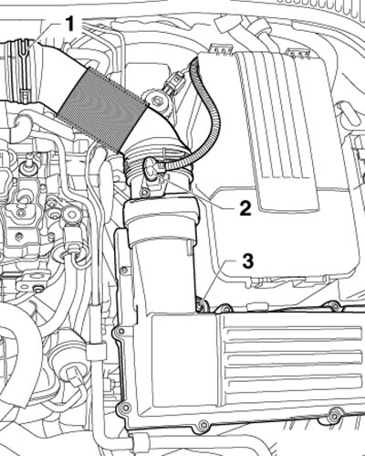
4.11. Removing the air cleaner of 1.8 L models
12. Installation is carried out in reverse order.
Diesel engines 2.0 l (CFHC, CFJA and CLCB)
13. The details of installation and assembly of the air cleaner are shown in the illustration.
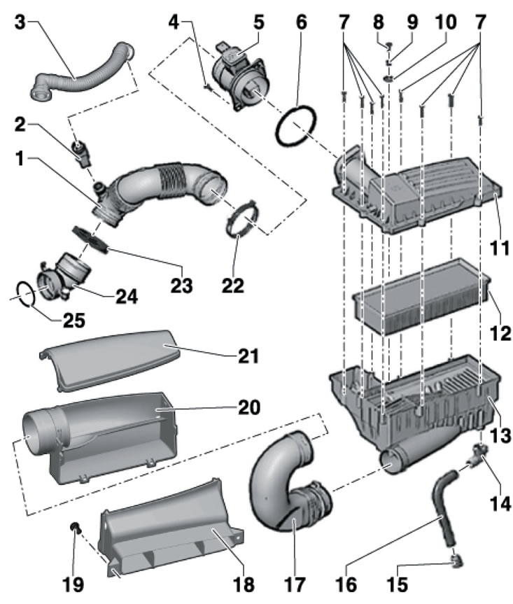
4.13. Installation and assembly details of the air cleaner for CFHC, CFJA and CLCB diesel engines 1. Inlet hose, to turbocharger; 2. Ventilation tube support, heated (only for countries with cold climates); 3. PCV connection pipe; 4, 19. Bolt, 2 Nm; 5. Air flow sensor "G70"; 6. Sealing ring; 7. Cover mounting bolts 11.2 Nm; 8. Housing mounting bolts 13.8 Nm; 9. Bushing; 10. Washer; 11. Air cleaner cover; 12. Filter element; 13. Air cleaner housing; 14. Connecting the drain hose; 15. Bypass valve; 16. Drainage hose; 17. Connecting hose; 18. Air intake, mounted on the hood lock holder; 20. Air intake duct; 21. Air duct cover 20; 22, 23. Spring plastic clamp; 24. Inlet connection, with locking screw, 9 Nm; 25. Sealing ring, subject to replacement
14. Remove the top engine cover.
15. Release the clamps (see illustration 3.18 Chapter 3) and remove the air intake duct cover.
16. Remove the bolts (arrows in illustration 3.19 Chapter 3) of the air intake duct (1) and remove the connecting hose (2) from the guide.
17. Press the latches (1 and 3 in Illustration 6.6 Chapter 3) and pull the connecting hose (4) out of the air cleaner (2).
18. Disconnect the connector (1 in the illustration) mAF sensor, disconnect the vacuum hose (3) and the turbocharger inlet hose (2). Loosen the bolt (4) and remove the air cleaner together with the MAF sensor.
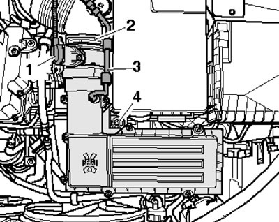
4.18. Removing the air cleaner
19. Installation is carried out in reverse order.