



Front suspension of the car Skoda Yeti

Suspension and steering — specifications
Tire inflation pressure - see Specifications to the Head " Controls and operating techniques " Maximum allowable play of the steering wheel on its outer rim with the engine running, mm — 30 Chassis PR number - 2UB PR...
Tire inflation pressure - see Specifications to the Head " Controls and operating techniques " Maximum allowable play of the steering wheel on its outer rim with the engine running, mm — 30 Chassis PR number - 2UB PR...
General information, recommendations and safety measures
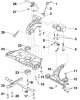
The independent front suspension is based on MacPherson struts and L-shaped lower arms connected to the subframe. Available with aluminum or steel subframe (see illustrations 1.1a-b). The steering knuckle assembly is...
The independent front suspension is based on MacPherson struts and L-shaped lower arms connected to the subframe. Available with aluminum or steel subframe (see illustrations 1.1a-b). The steering knuckle assembly is...

Unloading the suspension
Note: If components with rubber bushings have been replaced or the bolts/nuts of these components have been loosened, the suspension must be in the unloaded position before tightening the fasteners. 1. Rubber bushings...
Note: If components with rubber bushings have been replaced or the bolts/nuts of these components have been loosened, the suspension must be in the unloaded position before tightening the fasteners. 1. Rubber bushings...

Work with the front suspension subframe
Work with the front suspension subframe 1. Subframe installation details are shown on illustrations 1.1a-b . The following steps are described for models with an aluminum subframe. Fixing the position of the subframe...
Work with the front suspension subframe 1. Subframe installation details are shown on illustrations 1.1a-b . The following steps are described for models with an aluminum subframe. Fixing the position of the subframe...

Removal and installation the ball joint and suspension arm
Replacing the ball joint 1. Remove the hub bolt ( see Section 2 Chapter 8 ). 2. Remove the front wheel. 3. Give the nuts ( see illustration 4.5 Chapter 8 ). 4. Pull the drive shaft out of the hub slightly. If available,...
Replacing the ball joint 1. Remove the hub bolt ( see Section 2 Chapter 8 ). 2. Remove the front wheel. 3. Give the nuts ( see illustration 4.5 Chapter 8 ). 4. Pull the drive shaft out of the hub slightly. If available,...

Removal and installation the anti-roll bar
1. Remove the front wheels. 2. Remove the screws (see illustration) and remove the cover behind the pedals. 5.2. Fastening the pad behind the pedals 3. Unscrew the bolt (1 in the illustration) and disconnect the joint...
1. Remove the front wheels. 2. Remove the screws (see illustration) and remove the cover behind the pedals. 5.2. Fastening the pad behind the pedals 3. Unscrew the bolt (1 in the illustration) and disconnect the joint...

Removal and installation the steering knuckle
1. Loosen the drive shaft to hub assembly mounting bolt ( see Section 2 Chapter 8 ). 2. Remove the wheel. 3. Remove the anchor bracket together with the brake caliper without disconnecting the brake hose and hang them...
1. Loosen the drive shaft to hub assembly mounting bolt ( see Section 2 Chapter 8 ). 2. Remove the wheel. 3. Remove the anchor bracket together with the brake caliper without disconnecting the brake hose and hang them...
Removal and installation the front suspension strut
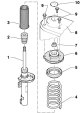
Removal and installation the rack 1. The suspension strut assembly details are shown in the illustration. 7.1. Suspension strut assembly parts 1. Shock absorber; 2. Rebound damper; 3. Protective sleeve; 4. Spring...
Removal and installation the rack 1. The suspension strut assembly details are shown in the illustration. 7.1. Suspension strut assembly parts 1. Shock absorber; 2. Rebound damper; 3. Protective sleeve; 4. Spring...
Removal and installation front adaptive suspension parts
1. Disconnect the sensor wiring connector, remove the nut ( 2 in illustration 5.7 Chapter 2 ) its fastening to the front suspension arm, unscrew the bolt (1) from the subframe and remove the sensor. 2. After...
1. Disconnect the sensor wiring connector, remove the nut ( 2 in illustration 5.7 Chapter 2 ) its fastening to the front suspension arm, unscrew the bolt (1) from the subframe and remove the sensor. 2. After...

Car Wheel Alignment Angles — General Information
Note: Only the toe-in of the front and rear wheels can be adjusted. 1. The geometry of the suspension and its rigidity determine the possibility of limiting the vertical movements of the body and reducing angular...
Note: Only the toe-in of the front and rear wheels can be adjusted. 1. The geometry of the suspension and its rigidity determine the possibility of limiting the vertical movements of the body and reducing angular...

Adjusting the camber and toe-in of the front wheels
Camber adjustment Note: Camber adjustment is not provided, but it can be aligned by moving the subframe. 1. Remove the sound insulation under the engine compartment ( see Chapter 11 ). 2. Loosen the bolts (1 in the...
Camber adjustment Note: Camber adjustment is not provided, but it can be aligned by moving the subframe. 1. Remove the sound insulation under the engine compartment ( see Chapter 11 ). 2. Loosen the bolts (1 in the...
This section is available on russian, bulgarian, belarusian, ukrainian, serbian, croatian, romanian, polish, slovak, hungarian
Read similar sections on other Skoda models
➧ Chassis (running gear): Front suspension Skoda Fabia 2 (2007-2014)
➧ Chassis (running gear): Front suspension Skoda Rapid 1 (2012-2022)
➧ Chassis (running gear): Front suspension Skoda Octavia 3 (2013-2019)
➧ Chassis (running gear): Front suspension Skoda Superb 2 (2008-2015)
➧ Chassis (running gear): Front suspension Skoda Kodiaq 1 (2016-2024)
Link to this section in various formats
TEXTHTMLBB Code
- General information
- Introduction to manual
- Controls and instruments
- Maintenance
- Power unit
- Petrol engine 1.2 l
- Petrol engine 1.4 l
- Petrol engine 1.8 l
- Diesel engine 2.0 l
- Cooling system
- Power and control system
- Exhaust system
- Ignition and preheating systems
- Starting and charging system
- Transmission
- Clutch
- Manual gearbox
- 7-speed gearbox DSG «0AM»
- 6-speed gearbox DSG «02E»
- Drive shafts
- Chassis (running gear)
- Brake system
- Front suspension
- Rear suspension
- Steering
- Body and interior
- Heating and air conditioning
- Exterior (external elements)
- Interior (internal elements)
- Electrical equipment
- Equipment and devices
- Lighting and signaling
- Electrical diagrams