



Petrol engine 1.2 l TSI (CBZB) of the car Skoda Yeti

Engine — Specifications
Petrol engine 1.2 l Type - Petrol, 4-cylinder, in-line, SOHC turbocharged Designation - CBZB The firing order of the cylinders is 1-3-4-2 Cylinder diameter // piston stroke, mm — 71.0 // 75.6 Cylinder capacity, cm³ →...
Petrol engine 1.2 l Type - Petrol, 4-cylinder, in-line, SOHC turbocharged Designation - CBZB The firing order of the cylinders is 1-3-4-2 Cylinder diameter // piston stroke, mm — 71.0 // 75.6 Cylinder capacity, cm³ →...

General information and preparatory operations
Note: This chapter describes the most typical and important engine maintenance and repair procedures, excluding procedures that require special skills and tools (for example, a major engine overhaul), - these works...
Note: This chapter describes the most typical and important engine maintenance and repair procedures, excluding procedures that require special skills and tools (for example, a major engine overhaul), - these works...

Checking the compression pressure
Note: An assistant will be required to check the compression pressure. If the engine is started with the fuses removed or the wiring disconnected, a corresponding fault code may be stored in the ECM memory and should...
Note: An assistant will be required to check the compression pressure. If the engine is started with the fuses removed or the wiring disconnected, a corresponding fault code may be stored in the ECM memory and should...

Checking the engine with a vacuum gauge
1. Using a vacuum gauge, you can get information about the condition of the engine and determine if the cylinder head gasket is blown, the fuel system, piston rings or valves are damaged, the fuel injection system is...
1. Using a vacuum gauge, you can get information about the condition of the engine and determine if the cylinder head gasket is blown, the fuel system, piston rings or valves are damaged, the fuel injection system is...

Checking engine oil pressure and the corresponding sensor
Note: Before checking, correct the engine oil level if necessary ( see Chapter 1 ). Engine oil pressure depends on many factors, such as its temperature and viscosity, crankshaft speed and the condition of the oil...
Note: Before checking, correct the engine oil level if necessary ( see Chapter 1 ). Engine oil pressure depends on many factors, such as its temperature and viscosity, crankshaft speed and the condition of the oil...
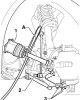
Removal and installation of the engine and its supports
Removal Note: The engine is removed downwards together with the transmission. All removed electrical wiring ties and clamps must be installed in their original places during installation. The electrical wiring and hoses...
Removal Note: The engine is removed downwards together with the transmission. All removed electrical wiring ties and clamps must be installed in their original places during installation. The electrical wiring and hoses...

Removal and installation the accessory drive belt and auxiliary brackets
1. The installation details of auxiliary units are shown in the illustration. 6.1. Installation details of auxiliary units (using the example of models with a refrigeration unit) 1. Drive belt; 2. Pulley bolt 3, subject...
1. The installation details of auxiliary units are shown in the illustration. 6.1. Installation details of auxiliary units (using the example of models with a refrigeration unit) 1. Drive belt; 2. Pulley bolt 3, subject...

Removal and installation timing belt covers
1. Timing drive installation details are shown in the illustration. 7.1 Timing drive parts 1. Cylinder head and its cover, machining of the mating surface is not allowed; 2. Cylinder block; 3. Lower auxiliary bracket...
1. Timing drive installation details are shown in the illustration. 7.1 Timing drive parts 1. Cylinder head and its cover, machining of the mating surface is not allowed; 2. Cylinder block; 3. Lower auxiliary bracket...

Replacing crankshaft seals, removing and installing flywheel and crankshaft pulley
1. The crankshaft oil seal installation details are shown in the illustration. 8.1. Crankshaft oil seal installation details 1. Pulley bolt 2, must be replaced, when tightening the thread must be lubricated, but the...
1. The crankshaft oil seal installation details are shown in the illustration. 8.1. Crankshaft oil seal installation details 1. Pulley bolt 2, must be replaced, when tightening the thread must be lubricated, but the...

Removal and installation the cylinder head, its cover and camshaft
1. The installation details and components of the cylinder head are shown in the illustration. 9.1. Cylinder head installation parts and components 1. Bolt, 8 Nm; 2. Fuel injection pump with valve "N276" for fuel...
1. The installation details and components of the cylinder head are shown in the illustration. 9.1. Cylinder head installation parts and components 1. Bolt, 8 Nm; 2. Fuel injection pump with valve "N276" for fuel...

Checking and adjusting the timing phases (setting TDC)
1. To check the position of piston No. 1 at TDC, follow the steps described in paragraphs 6-10 Section 9 and pay attention to the groove on the end of the camshaft: it should be located as shown in the illustration. It...
1. To check the position of piston No. 1 at TDC, follow the steps described in paragraphs 6-10 Section 9 and pay attention to the groove on the end of the camshaft: it should be located as shown in the illustration. It...

Removal and installation the timing chain and oil pump drive chain
1. Front right wheel arch liner and sound insulation under the engine compartment ( see Chapter 11 ). 2. Remove the drive belt ( see Section 6 ). 3. Remove the upper timing belt cover (see section 7). 4. Follow the...
1. Front right wheel arch liner and sound insulation under the engine compartment ( see Chapter 11 ). 2. Remove the drive belt ( see Section 6 ). 3. Remove the upper timing belt cover (see section 7). 4. Follow the...

Work with the gas distribution mechanism
1. The design of the timing belt is shown in the illustration. 12.1. Timing belt parts 1. Bolt, subject to replacement, 50 Nm, then tighten to an angle of 90°; 2. Camshaft sprocket; 3. Bolt, 10 Nm; 4. CMP sensor with...
1. The design of the timing belt is shown in the illustration. 12.1. Timing belt parts 1. Bolt, subject to replacement, 50 Nm, then tighten to an angle of 90°; 2. Camshaft sprocket; 3. Bolt, 10 Nm; 4. CMP sensor with...

Removal and installation the oil pan, oil pump and oil cooler
1. The engine lubrication system parts are shown in the illustration. 13.1. Engine lubrication system parts 1. Filler cap; 2. Oil supply pipe to the turbocharger; 3. Dipstick for measuring engine oil level; 4. Upper...
1. The engine lubrication system parts are shown in the illustration. 13.1. Engine lubrication system parts 1. Filler cap; 2. Oil supply pipe to the turbocharger; 3. Dipstick for measuring engine oil level; 4. Upper...
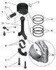
Features of engine overhaul
Caution: The presence of metal shavings or large quantities of small metal particles found during engine rebuild may indicate damage to the crankshaft and connecting rod bearings. To prevent further damage, thoroughly...
Caution: The presence of metal shavings or large quantities of small metal particles found during engine rebuild may indicate damage to the crankshaft and connecting rod bearings. To prevent further damage, thoroughly...
This section is available on russian, bulgarian, belarusian, ukrainian, serbian, croatian, romanian, polish, slovak, hungarian
Read similar sections on other Skoda models
➧ Power unit: Petrol engines Skoda Rapid 1 (2012-2022)
➧ Power unit: Petrol engines 1.8/2.0 l Skoda Superb 2 (2008-2015)
➧ Power unit: Petrol engine 1.4 l Skoda Kodiaq 1 (2016-2024)
➧ Power unit: Petrol engine 1.6 l Skoda Felicia (1994-2001)
Link to this section in various formats
TEXTHTMLBB Code
- General information
- Introduction to manual
- Controls and instruments
- Maintenance
- Power unit
- Petrol engine 1.2 l
- Petrol engine 1.4 l
- Petrol engine 1.8 l
- Diesel engine 2.0 l
- Cooling system
- Power and control system
- Exhaust system
- Ignition and preheating systems
- Starting and charging system
- Transmission
- Clutch
- Manual gearbox
- 7-speed gearbox DSG «0AM»
- 6-speed gearbox DSG «02E»
- Drive shafts
- Chassis (running gear)
- Brake system
- Front suspension
- Rear suspension
- Steering
- Body and interior
- Heating and air conditioning
- Exterior (external elements)
- Interior (internal elements)
- Electrical equipment
- Equipment and devices
- Lighting and signaling
- Electrical diagrams