



Note: All electrical wiring ties must be installed in their original locations. The wiring harness is removed together with the climate control system housing.
1. On some engines, it may be necessary to remove the top engine cover to gain access to the expansion valve (see Chapter 2), turbocharger inlet hose, diesel particulate filter cover and air cleaner inlet hose (see Chapter 4).
2. Drain the refrigerant.
3. Disconnect the negative cable from the battery.
4. Remove the center console, instrument panel and lower trim of the right A-pillar (see Chapter 11).
5. Remove the expansion valve cap (see Section 18, if available).
6. Clamp the coolant hoses (1 in illustration 13.2) heater radiator, mark them, pull out the clamps and disconnect the hoses from the radiator, collecting the leaking coolant. If the radiator is supposed to be replaced, the coolant should also be replaced, so in this case it can be drained (see Section 2).
7. Connect the compressor to the upper fitting of the heater radiator (1 in illustration 13.3) and blow out the remaining coolant from the radiator (3) into a previously prepared container (2).
8. Remove the bolts (1 in the illustration) refrigerant line fasteners (2) and disconnect them from the expansion valve (3). Seal the connections to prevent dirt from entering the refrigerant circuit.
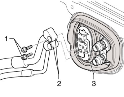
15.8. Bolts (1) for fastening refrigerant lines (2)
10. Cover the flooring under the heater radiator with waterproof material and absorbent paper.
11. Remove the beam (8 in the illustration) instrument panels (see Chapter 11), pull out and remove the wiring harness from the climate control system housing. Remove the wiring harness from the holder (5).
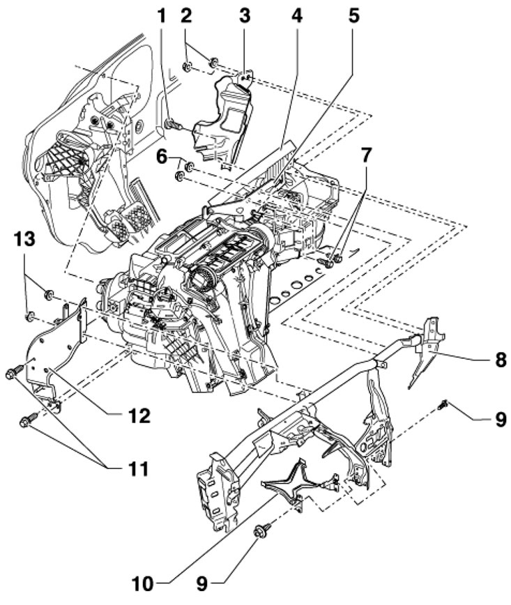
15.11. Climate system housing fastening parts 1. Bolt, 4.5 Nm; 2. Nuts, 2 pcs., 4.5 Nm; 3. Wiring Holder; 4. Climate system housing; 5. Right bracket; 6, 13. Nuts, 8 Nm; 7.11. Bolts, 8 Nm; 8. Instrument panel beam; 9. Bolt, 2 Nm; 10. Support; 12. Left bracket
12. Remove the diagnostic interface J533 (see Chapter 12).
13. Tilt the climate control housing slightly and remove it from the rear air duct upwards. Remove the climate control system housing from the vehicle, carefully removing the wiring harness from the right bracket.
14. If it is necessary to disassemble the housing, follow the instructions. illustrations.
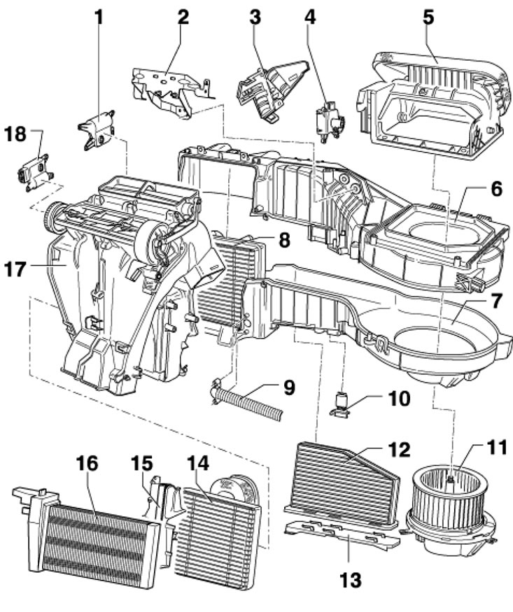
15.14a. Assembly details of the "Climatic" climate system housing 1. Temperature flap actuator V68; 2. Bracket; 3. Lid; 4. Activator V113 of the circulation flap; 5. Air intake, with recirculation flap; 6/7. Upper/lower part of the evaporator casing; 8. Evaporator; 9. Glove box cooling hose, not installed from week 46 of 2010; 10. Assembly of resistors N24 fans 11; 11. Fan V2; 12. Diesel particulate filter; 13. Filter cover 12; 14. Heater radiator; 15. Radiator cap 14; 16. Auxiliary heating element Z35, on some diesel models; 17. Distribution casing; 18. Activator; V145 Front camshaft
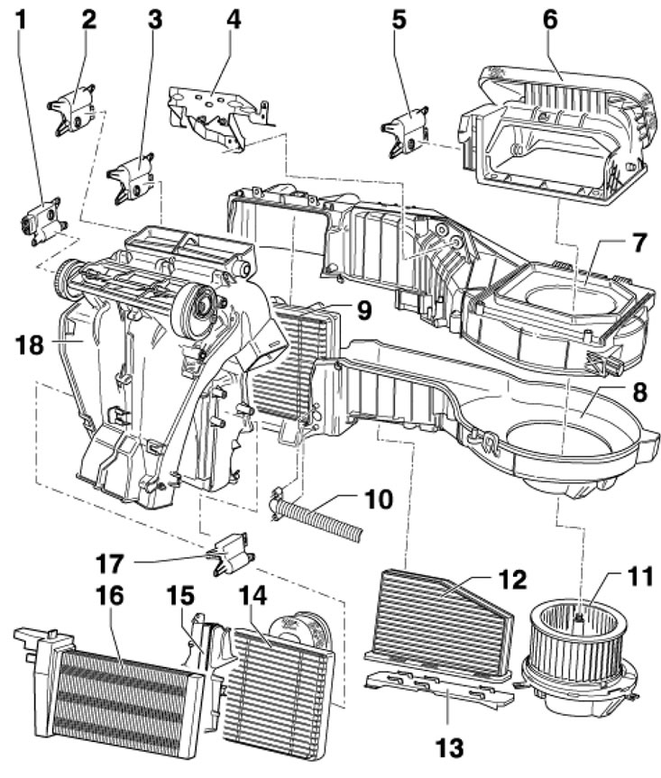
15.14b. Climate system housing assembly parts "Climatronic" 1. V426 Activator Front Distribution Valve; 2. Activator V158 left temperature flap; 3. Activator V107 for glass blower flap; 4. Bracket; 5. V425 Activator of the circulation flap; 6. Air intake, with recirculation flap; 7/8. Upper/lower part of the evaporator casing; 9. Evaporator; 10. Glove box cooling hose; 11. Fan V2 with control unit J126; 12. Diesel particulate filter; 13. Filter cover 12; 14. Heater radiator; 15. Radiator cap 14; 16. Auxiliary heating element "Z35", on some diesel models; 17. V159 actuator right temperature flap; 18. Distribution casing
15. Installation is carried out in reverse order. When installing, have an assistant guide both coolant pipes from the engine compartment. Use new expansion valve O-rings.