



Power supply and engine control system Skoda Yeti

Fuel, Engine Management and Exhaust Systems — Specifications
Compliance with toxicity standards Petrol engine 1.2 l CBZB - Euro 5 Petrol engine 1.4 l SAHA - Euro 5 Petrol engine 1.8 l CDAA - Euro 5, EU-2 DDK Petrol engine 1.8 l CDAB — Euro 4, EU-2/BS3, meets Euro 5 requirements...
Compliance with toxicity standards Petrol engine 1.2 l CBZB - Euro 5 Petrol engine 1.4 l SAHA - Euro 5 Petrol engine 1.8 l CDAA - Euro 5, EU-2 DDK Petrol engine 1.8 l CDAB — Euro 4, EU-2/BS3, meets Euro 5 requirements...

General information and safety precautions: power supply system
Fuel supply Petrol models The fuel system consists of a rear-mounted fuel tank with a filler neck, a fuel supply module with a fuel gauge, a fuel gauge #2 with a jet pump, a carbon fuel vapor absorber, fuel lines, a...
Fuel supply Petrol models The fuel system consists of a rear-mounted fuel tank with a filler neck, a fuel supply module with a fuel gauge, a fuel gauge #2 with a jet pump, a carbon fuel vapor absorber, fuel lines, a...
Operating principles of the engine management system
Since the power supply system is part of the engine management system, which also includes exhaust gas (exhaust gas) toxicity reduction systems, it is not possible to consider them separately. The main element of the...
Since the power supply system is part of the engine management system, which also includes exhaust gas (exhaust gas) toxicity reduction systems, it is not possible to consider them separately. The main element of the...

Basic fuel system maintenance procedures
Relieving fuel pressure in the low-pressure circuit of gasoline models Please note: The pressure in the low-pressure circuit of FSI models can reach 6 bar! 1. Remove the fuel pump or fuel pump control unit fuse from the...
Relieving fuel pressure in the low-pressure circuit of gasoline models Please note: The pressure in the low-pressure circuit of FSI models can reach 6 bar! 1. Remove the fuel pump or fuel pump control unit fuse from the...

Removal and installation the air cleaner, replacing its filter element
1. Description of replacement of the filter element is given in Section 16 Chapter 1 . The following describes the procedure for removing the air cleaner assembly. Petrol engines 1.2 and 1.4 l Note: The description of...
1. Description of replacement of the filter element is given in Section 16 Chapter 1 . The following describes the procedure for removing the air cleaner assembly. Petrol engines 1.2 and 1.4 l Note: The description of...

Removal and installation of turbocharger and exhaust manifold assembly, vacuum block work
Note: If a mechanical fault is detected in the turbocharger (for example, damage to compressor blades), in addition to replacing the turbocharger assembly itself, to prevent subsequent damage, you should make sure that...
Note: If a mechanical fault is detected in the turbocharger (for example, damage to compressor blades), in addition to replacing the turbocharger assembly itself, to prevent subsequent damage, you should make sure that...

Removal and installation the intercooler
Engine 1.2 l 1. The intercooler installation details are shown in the illustration. The radiator for the intercooler is combined with the radiator of the engine cooling system; description of radiator...
Engine 1.2 l 1. The intercooler installation details are shown in the illustration. The radiator for the intercooler is combined with the radiator of the engine cooling system; description of radiator...

Removal and installation the throttle valve and intake manifold
Engine 1.2 l 1. The installation details of the intake manifold and throttle module are shown in the illustrations. 7.1a. 1.2L Engine Intake Manifold and Throttle Valve Installation Details, Part 1 of 2 1. Connecting...
Engine 1.2 l 1. The installation details of the intake manifold and throttle module are shown in the illustrations. 7.1a. 1.2L Engine Intake Manifold and Throttle Valve Installation Details, Part 1 of 2 1. Connecting...
Removal and installation the gas pedal
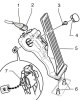
1. Remove the steering column cover behind the pedals (see illustration). 8.1. Casing fasteners behind pedals 2. Pry off the plug with a screwdriver (4 in the illustration) and unscrew the bolt (3) located behind it....
1. Remove the steering column cover behind the pedals (see illustration). 8.1. Casing fasteners behind pedals 2. Pry off the plug with a screwdriver (4 in the illustration) and unscrew the bolt (3) located behind it....

Removal and installation of fuel injection system parts, except for the high-pressure fuel pump
Caution: After disconnecting the fuel lines, plug the exposed holes to prevent dirt from entering the fuel supply system. 1.2L Engine: Injector Replacement 1. Details of the installation of the fuel distribution line...
Caution: After disconnecting the fuel lines, plug the exposed holes to prevent dirt from entering the fuel supply system. 1.2L Engine: Injector Replacement 1. Details of the installation of the fuel distribution line...

Removal and installation of fuel injection pump
Caution: After disconnecting the fuel lines, plug the exposed holes to prevent dirt from entering the fuel supply system. Engine 1.2 l Note: When removing/installing the fuel injection pump, grasp only its body. If the...
Caution: After disconnecting the fuel lines, plug the exposed holes to prevent dirt from entering the fuel supply system. Engine 1.2 l Note: When removing/installing the fuel injection pump, grasp only its body. If the...

Removal and installation the fuel tank
Petrol models 1. The installation details of the fuel tank and its components are shown in the illustrations. 11.1a. Fuel tank installation details and its components (petrol models up to 06.2010.) 1. Fuel supply line,...
Petrol models 1. The installation details of the fuel tank and its components are shown in the illustrations. 11.1a. Fuel tank installation details and its components (petrol models up to 06.2010.) 1. Fuel supply line,...

Removal and installation the fuel supply module, jet pump and fuel level sensors
Fuel Delivery Module and Fuel Supply Sensor "G" 1. Make sure the tank is no more than 1/3 full. If necessary, pump out the fuel ( see Section 3 ). 2. Turn off the ignition and electrical appliances, remove the key from...
Fuel Delivery Module and Fuel Supply Sensor "G" 1. Make sure the tank is no more than 1/3 full. If necessary, pump out the fuel ( see Section 3 ). 2. Turn off the ignition and electrical appliances, remove the key from...

Removal and installation fuel filters
1. The installation details of fuel filters are shown in the illustrations. Description of replacement of filter element of diesel models is given in Section 23 Chapter 1 . 13.1a. Fuel filter installation details for...
1. The installation details of fuel filters are shown in the illustrations. Description of replacement of filter element of diesel models is given in Section 23 Chapter 1 . 13.1a. Fuel filter installation details for...
This section is available on russian, bulgarian, belarusian, ukrainian, serbian, croatian, romanian, polish, slovak, hungarian
Read similar sections on other Skoda models
➧ Petrol engines 1.2 l: Power and control system Skoda Fabia 2 (2007-2014)
➧ Power unit: Power and control system Skoda Rapid 1 (2012-2022)
➧ Diesel engines 1.6/2.0 l: Supply system Skoda Octavia 3 (2013-2019)
➧ Power unit: Power and exhaust system Skoda Superb 2 (2008-2015)
➧ Power unit: Diesel power system Skoda Felicia (1994-2001)
Link to this section in various formats
TEXTHTMLBB Code
- General information
- Introduction to manual
- Controls and instruments
- Maintenance
- Power unit
- Petrol engine 1.2 l
- Petrol engine 1.4 l
- Petrol engine 1.8 l
- Diesel engine 2.0 l
- Cooling system
- Power and control system
- Exhaust system
- Ignition and preheating systems
- Starting and charging system
- Transmission
- Clutch
- Manual gearbox
- 7-speed gearbox DSG «0AM»
- 6-speed gearbox DSG «02E»
- Drive shafts
- Chassis (running gear)
- Brake system
- Front suspension
- Rear suspension
- Steering
- Body and interior
- Heating and air conditioning
- Exterior (external elements)
- Interior (internal elements)
- Electrical equipment
- Equipment and devices
- Lighting and signaling
- Electrical diagrams