



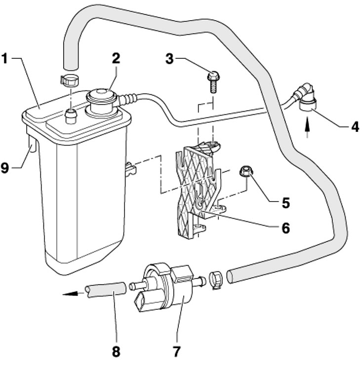
15.1a. Installation details of the EVAP canister for 1.2 and 1.4 L engines 1. The carbon canister, in the right front part of the engine compartment, is held in the groove of the bracket 6; 2. Pressure holding valve with connecting hose; 3. Bolt, 8 Nm; 4. Ventilation line, from the fuel tank; 5. Nut, 8 Nm; 6. Bracket; 7. E/m drip No. 1 "N80" for purge EVAP canister; 8. Connecting hose, to the intake manifold; 9. Air inlet connection
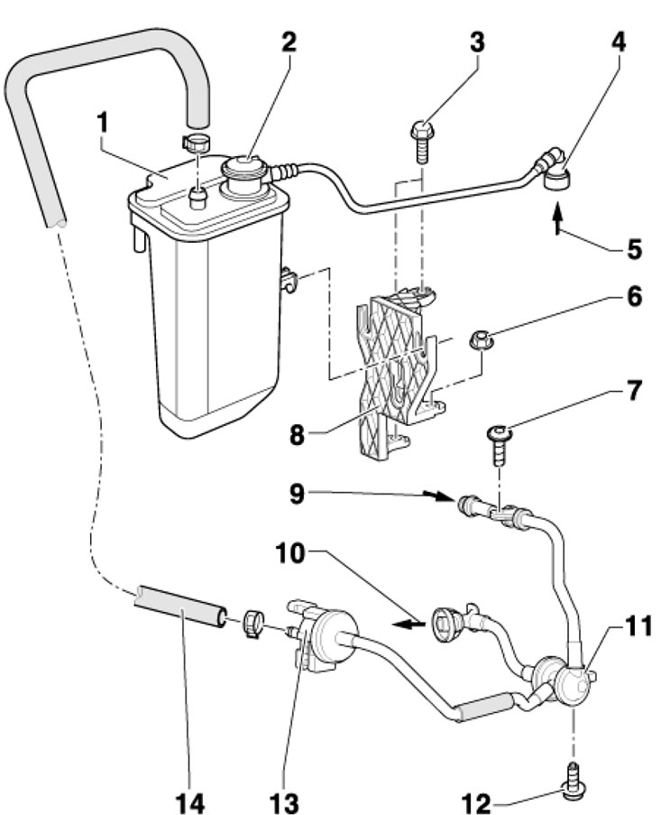
15.1b. EVAP canister installation details for 1.8L engines 1. The carbon canister, in the right front part of the engine compartment, is held in the groove of the bracket 6; 2. Pressure holding valve with connecting hose; 3. Bolt, 8 Nm; 4, 14. Connecting hose 5 From the fuel tank; 6. Nut, 8 Nm; 7. Bolt, 5 Nm; 8. Bracket; 9. From a turbocharger; 10. To the intake manifold; 11. Double non-return valve, combined with valve 13; 12. Bolt, 12 Nm; 13. E/m drip No. 1 "N80" for purge EVAP canister, combined with valve 11