



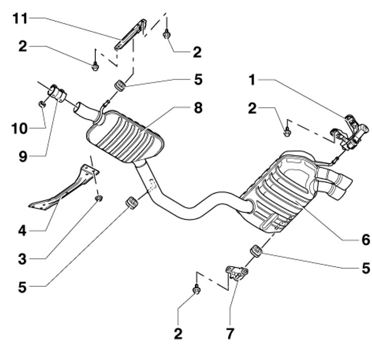
17.1a. Installation details of the middle and rear mufflers of 1.2 l models up to 06.2010. 1, 7, 11. Suspension; 2. Bolt, 23 Nm; 3. Nut, 20 Nm; 4. Central tunnel cross member; 5. Rubber suspension; 6. Rear muffler; 8. Middle muffler; 9. Double clamp, 23 Nm; 10. Nut, 23 Nm
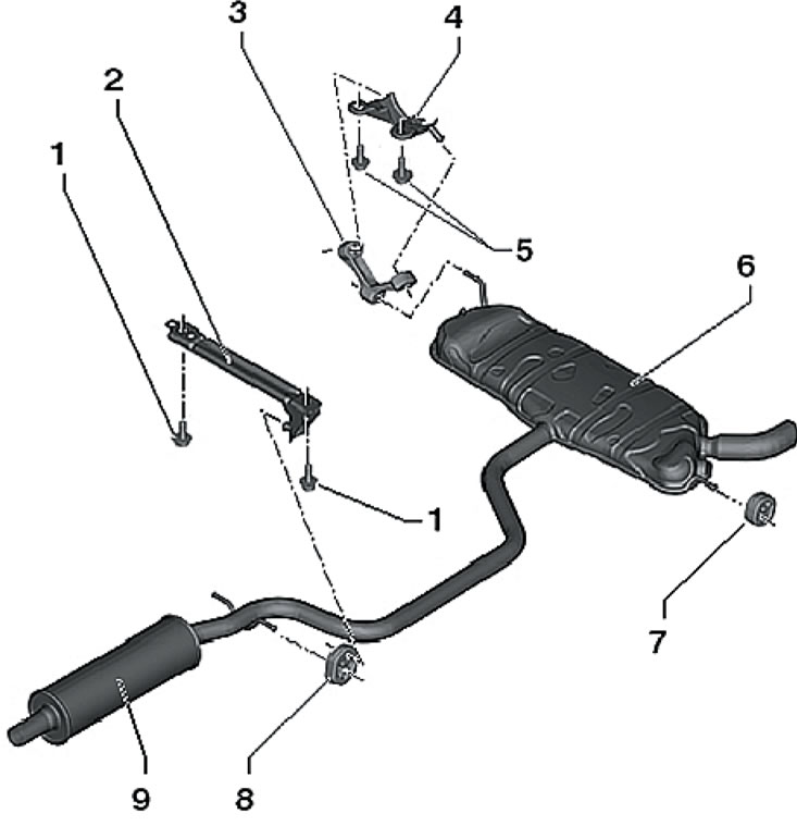
17.1b. Installation details of the middle and rear mufflers of 1.2 l models from 06.2010. 1.5. Bolt, 23 Nm; 2.4. Suspension; 3, 7, 8. Rubber suspension; 6. Rear muffler; 9. Middle muffler
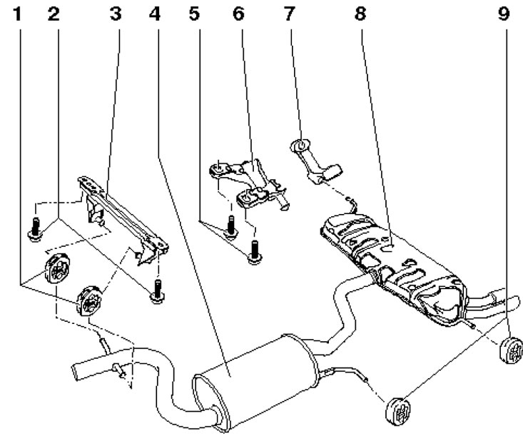
17.1s. Installation details of the middle and rear mufflers of the 1.4 l models 1, 7, 9. Rubber suspension; 2.5. Bolt, 23 Nm; 3, 6. Suspension; 4. Middle muffler; 8. Rear muffler
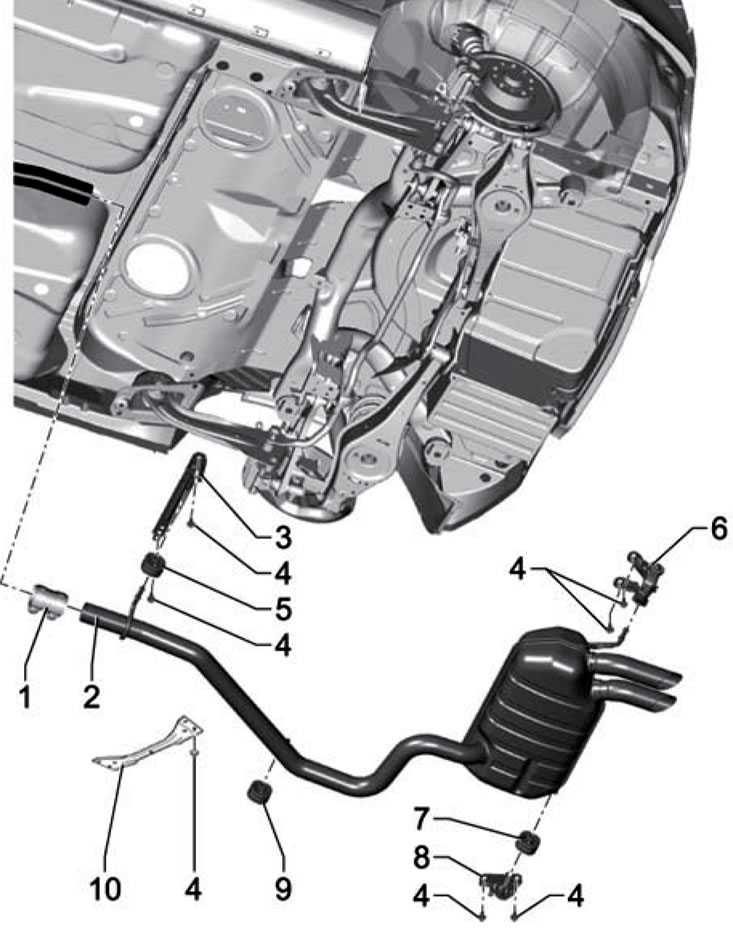
17.1d. 2.0L Models Rear Exhaust Pipe Installation Details (cFHC, CFJA and CLCB engines) 1. Double clamp, 25 Nm; 2. Rear muffler; 3, 6. Suspension; 4. Bolt, 25 Nm; 5, 7, 9. Rubber suspension; 8. The exhaust pipe bracket is firmly riveted together with the heat shield to the fuel tank; 10. Central tunnel cross member
2. On petrol models, the middle and rear mufflers are installed at the factory as a single unit. If necessary, after removing the muffler assembly, they can be replaced individually by cutting the pipe and connecting its parts with a clamp, as described below.
3. Place of incision (2 in the illustration) marked on the outer surface of the pipe. Markers (1 and 3) indicate the installation locations of the double clamp (4).
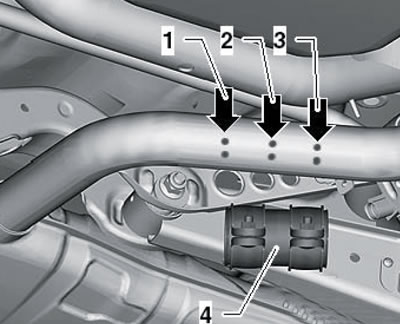
17.3. Cutting mark (2) and clamp installation marks (1 and 3) (4)
4. The ends of the clamp bolts must not be lower than the bottom point of the pipe. The rear muffler should be positioned so that the distances (and in the illustrations) between the pipe and the bumper were equal to each other, and the distance (b in illustration 17.4b) was equal for both pipes.
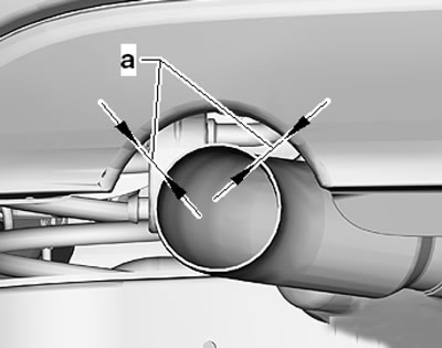
17.4a. Rear muffler alignment (since 06.2010.)
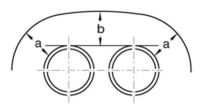
17.4b. Rear Muffler Alignment (until 06.2010.)
5. To position the exhaust pipe without tension, loosen the double clamp nuts (1 in illustration 17.5a) and correctly set the intermediate relative to the mark at a distance (a) = 5 mm and tighten the nuts by hand. Then push the exhaust pipe forward so that the distance (and in illustration 17.5b) between the suspension/body and the sub-suspension/middle muffler was 7-9 mm. Then tighten the double clamp nuts with a force of 23 Nm.
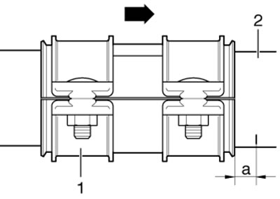
17.5a. Position of the clamp (the arrow points forward)
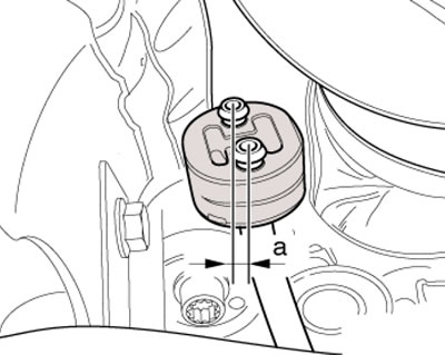
17.5b. Pre-tensioning of the support
Replacing the exhaust pipe of 1.8L models
6. Remove the air cleaner (see Section 4).
7. Remove the connector from the bracket (1 in the illustration) lambda probe "G39" and disconnect it.
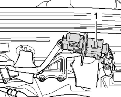
17.7. Lambda probe connector "G39"
8. Give the nuts (see illustration) and bend down the bottom trim on the right inner side.
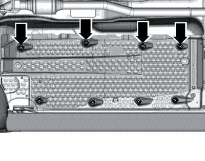
17.8. Fastening the bottom lining
9. Unhook the rope (arrow on the illustration), remove the bracket (1) and disconnect the lambda probe connector "G130".
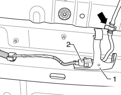
17.9. Lambda probe connector "G130"
10. Remove the driveshaft (see Chapter 8), Remove both upper and then both lower nuts securing the exhaust pipe to the catalytic converter (see illustration).
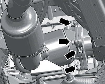
17.10. Nuts for fastening the exhaust pipe to the catalytic converter
11. Remove the bolts (see illustration) and remove the exhaust pipe bracket.
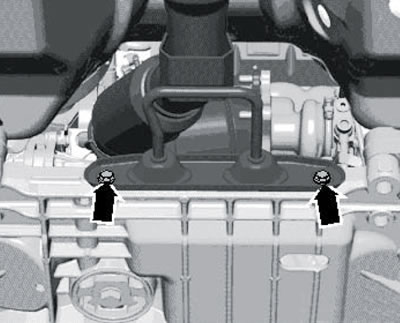
17.11. Suspension fastening
12. Give the nuts (arrows on the illustration) and remove the front cross member of the central tunnel. Loosen the double clamp (1), slide it back and remove the exhaust pipe, making sure that its flexible section is not bent more than 10°.
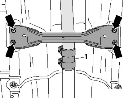
17.12. Central tunnel crossmember fastener and exhaust pipe clamp
13. Installation is carried out in reverse order. Use new gaskets and self-locking nuts. Before tightening the nuts, apply high-temperature grease G052 112AZ to the studs. Finally, set the exhaust system to be voltage-free (see paragraphs 4-5).