



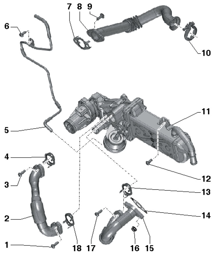
18.1. Installation details of EGR system components (cFHC, CFJA and CLCB engines) 1, 3, 6. Bolt, 9 Nm; 2. Connecting pipe, to cylinder head, with flexible connection; 4, 7. Gasket, subject to replacement; 5. Vacuum line, do not change the curvature; 8. Connecting tube, to the inlet pipe, with flexible connection; 9, 12, 17. Bolt, 9 Nm; 10. Clamp, 5 Nm; 11. EGR radiator; 13, 14, 18. Gasket, subject to replacement; 15. Connecting pipe, from the exhaust manifold, with flexible connection; 16. Nut, 22 Nm
2. The location of the components involved in regulating the exhaust gas temperature is shown in the illustration. Before installing the old lambda probe or exhaust gas temperature sensor, apply high-temperature grease G052 112A2 to its threads, making sure that it does not get into the openings in the lambda probe housing.
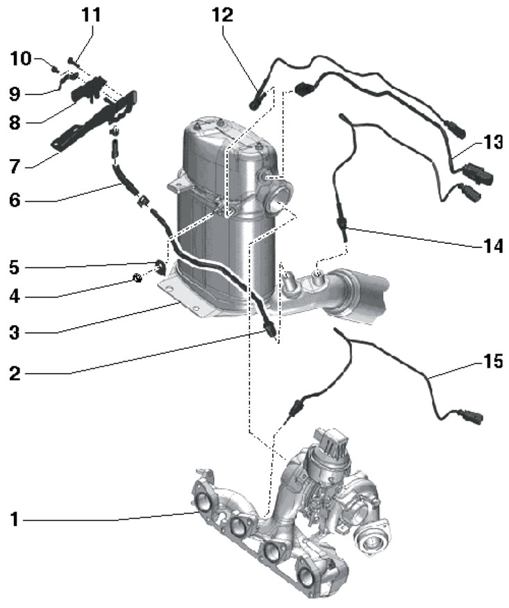
18.2. Location of components involved in regulating exhaust gas temperature (cFHC, CFJA and CLCB engines) 1. Turbocharger with exhaust manifold; 2. Pressure (control) line, 45 Nm; 3. Diesel particulate filter; 4. Nut, 9 Nm; 5, 9. Bracket; 6. Hose; 7. Sensor bracket 8; 8. Differential pressure sensor "G505", disconnect the hoses from it only when replacing, place the sensor so that it does not touch other parts; 10. Bolt, 5 Nm; 11. Bolt, 8 Nm; 12. Sensor No. 3 "G495" exhaust gas temperature, 45 Nm; 13. Lambda probe "G39", 50 Nm; 14. Sensor No. 4 "G648" exhaust gas temperature, 45 Nm; 15. Sensor No. 1 "G235" exhaust gas temperature, 45 Nm
Information copied from the resource: www.skodabook.ru