
Note: The description is given on the example of manual transmission "02Q" (AWD models).
Note: When removing, remember the layout of hoses, pipes, electrical wiring, etc., so that you can lay them in the same way.
1. Disconnect the negative cable from the battery.
2. Remove the air cleaner (see chapter 4).
3. Remove the battery and its holder (see chapter 5).
4. Remove retaining ring (3 in illustration 4.16) gear selector cable from the gear selector lever (1) and remove the cable from the pin (arrow). On models with a metal lever (2) select the groove, remove the retaining ring (4) groove selection cable and remove the cable from the pin (arrow).
5. On models with a plastic slot selection cable, remove the cable lock in the lug (see paragraphs 5 of Section 4).
6. Give fasteners (see illustration 4.18), remove the cable holder from the manual transmission, set it aside and tie it up. If available, remove the soundproofing under the engine compartment (see chapter 11).
7. If present, remove the ventilation tube from the corner drive (see resist. illustration).
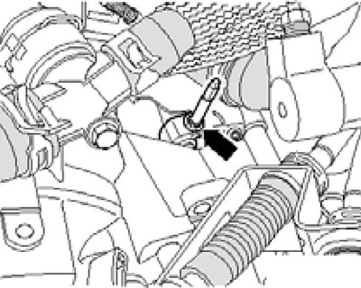
5.7 Corner gear breather
8. A line in the form of a tube / hose or a plastic line can be installed between the clutch master cylinder and the bleeder valve. If a plastic line is installed, the plastic return hose (3 on resist. illustrations) must be removed from the master cylinder and plugged. Do not pinch the plastic hose as it will in doing so, it may be damaged. After disconnecting the hydraulic clutch line, do not depress the clutch pedal.
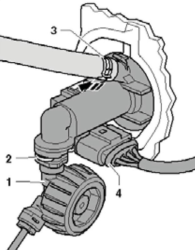
5.8 Brake fluid connections
9. If a tube/hose line is installed, pinch the hose (And on the opposite illustrations), going to the main cylinder, with an MP7-602 or No. 3094 clamp, remove the retainer until it stops (arrow), disconnect the clutch hydraulic line from the slave cylinder/bleeder port and plug it. After disconnecting the hydraulic clutch line, do not depress the clutch pedal.
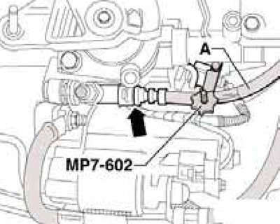
5.9 Clutch line connection
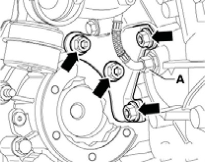
10. Disconnect the max wire from the starter (1 per resist. illustrations), disconnect the connector (2) D / V reversing lights and starter connectors. Turn out the top connecting bolts of transmission/engine and the top bolt of a starter.
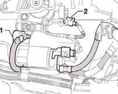
5.10 Wiring connections in the starter area
11. Remove the filling pieces from the upper edges of both wings. If present, remove the connections located in the area of the engine lifting lug. Screw bracket T10346 into the rear of the three holes in the battery holder using an M6 bolt or one of the battery holder bolts (see resist. illustration). Install supports MP9-200 (№10-222A) behind the hood pillar so that their heel is positioned as illustrated (see callout), behind the bolt (1) and on the side of the bolt (2). Hook the support spindles to bracket T10346 and to the front left engine lifting eye. Slightly unload the supports of the power unit without lifting it from the supports.
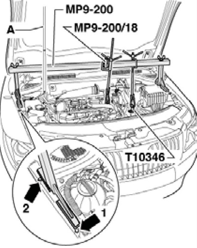
5.11 Hanging out the power unit
12. Remove the front wheels and sound insulation under the engine compartment.
13. Remove the starter bracket and the starter itself (see chapter 5).
14. Disconnect the connector (2 to resist. illustrations) boost pressure sensor ''G41", remove the bolt (4) and remove the air duct between the intercooler and the intake manifold by slightly lifting the clamps (1 and 3).
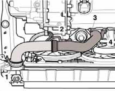
5.14 Removing the tube between the intercooler and the intake manifold
15. Disconnect the connector (1 in Illustration 15.16 of Chapter 2), remove the bolts (arrows) and remove the fan shroud.
16. Remove all exhaust system supports from the manual transmission and exhaust pipe (see chapter 4).
17. Disconnect the exhaust system on the clamp and remove the exhaust system bracket from the subframe. Tie up the exhaust pipe.
Note: Do not bend the flexible section of the exhaust pipe more than 10°to avoid damaging it.
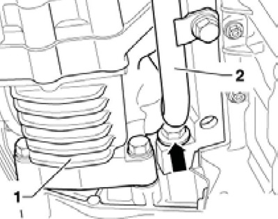
18. If available, remove the drive shaft cover (see resist. illustration).
5.18 Fixing the drive shaft cover
19. Mark the position of the cardan shaft with a flexible disk relative to the output flange of the angular transmission, and then fasten the propeller shaft to the output flange of the angular transmission (see resist. illustration).
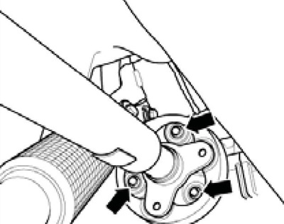
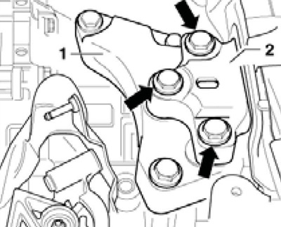
5.19 Fixing the cardan shaft on the bevel gear
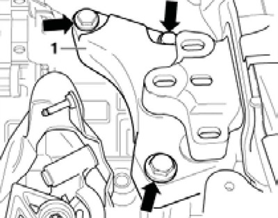
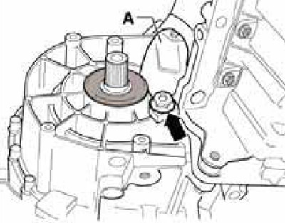
20. Remove the swing support from the manual transmission by unscrewing the bolts (B and C to resist. illustrations).
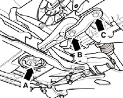
5.20 Fixing the oscillating support
21. After removing the rocker from the manual transmission, the power unit leans forward slightly, so be careful not to damage the gasket (see resist. illustration) in the driveshaft flange. Press the power unit forward, pull the cardan shaft off the angle drive flange, lift the cardan shaft and tie it on the body.
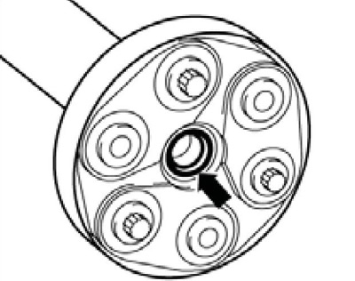
5.21 PTO shaft flange seal
22. Disconnect the engine oil temperature and level sensor connector on the underside of the engine oil pan (see chapter 2).
23. Disconnect the connector of the front left suspension height sensor, give the nut (2 to resist. illustrations), remove the bolt (1) and remove the sensor.
5.23 Sensor "G78" front suspension height
24. Fix the subframe and remove it together with the console without steering gear, left arm and anti-roll bar (see chapter 10).
25. Remove the front drive shafts from the flanged shafts (see chapter 8). Tie up the drive shaft on the front suspension spring so that it does not kink at the pivot. Be careful not to damage the shaft cover.
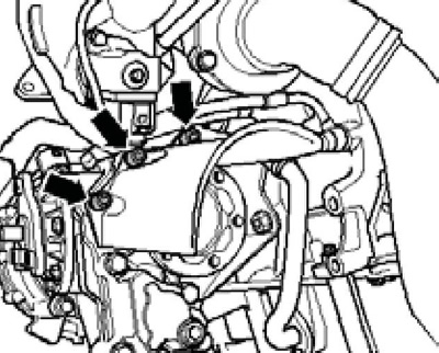
26. On models without a particulate filter, remove the turbocharger oil line from the engine (And on the opposite illustrations), give fasteners (arrows) and remove the support between the motor and the bevel gear.
5.26 Oil line (A) and fasteners for the corner gear bracket
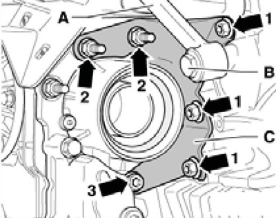
27. On models with a particulate filter, remove it together with the bracket and unscrew the bolts (1-3 per resist. illustrations) fastening of the support between the engine and the corner gear.
Note: The support can only be removed after the manual transmission has been separated from the engine.
5.27 Gearbox holder fastener
28. On models with an additional heater, it is necessary to remove the corner gear (1 per resist. illustrations), as described in Chapter 8. Otherwise the tube will be damaged (2) additional heater. Connecting bolt engine / manual transmission (arrow) can be removed from the cylinder block only after removing the tube (2).
5.28 Corner drive on models with auxiliary heater
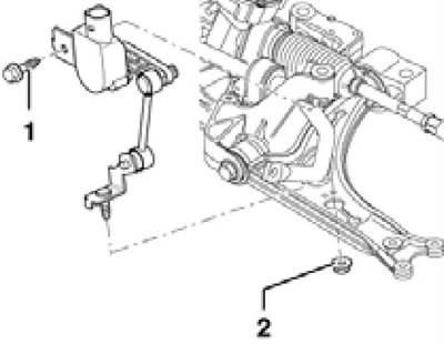
29. Remove the bolts (arrows on resist. illustrations) support fastenings (2) manual transmission to console (1).
5.29 Bolts for fastening the manual transmission support to the console
30. Lower the manual transmission on the MP9-200 tool spindle so that the distance (and on the opposite illustrations) was approximately 60 mm.
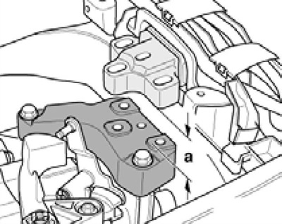
5.30 Dimension for manual transmission lowering
31. Remove the bolts (arrows on resist. illustrations) console mounts (1) and remove it from the gearbox.
5.31 Console bolts
32. Remove the groove selection lever. On models with a metal lever (1 per resist. illustrations) select the groove, remove the retaining ring (arrow) and remove the lever. For a description of the removal of the plastic lever, see Section 4.
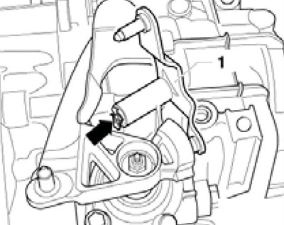
5.32 Retaining ring of the metal slot selector lever
33. Remove the gear selector lever from the selector shaft (see Section 4).
34. Remove the lower bolts securing the manual transmission to the engine.
35. Attach support #3282 with plate #3282/33 to the transmission jack (see resist. illustration). Fix the MPZ-419/40 adapter in the threaded hole of the manual transmission, screw the bolt No. 3282/29 into the mounting hole of the oscillating support, and also screw the M10x20 bolt (A). Remove the bolt (WITH) manual transmission mounts.
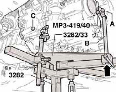
5.35 Installing the gearbox removal support and bolt (3) manual transmission mounts
36. On models with an additional heater, remove the bolt (1 per resist. illustrations) and gently squeeze the tube (2) away from the engine in the direction of the arrow.
5.36 Separation of the auxiliary heater pipe from the engine
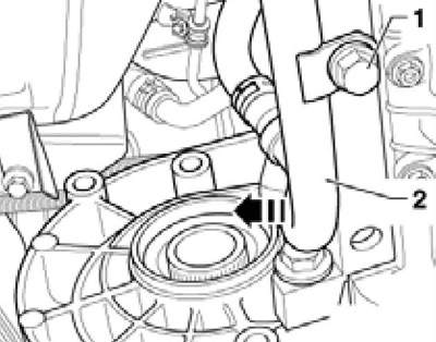
37. Remove the small cover (And on the opposite illustrations) flywheel, remove the bolt (arrow) fixing the manual transmission and press the manual transmission from the engine (on centering bushes).
5.37 Flywheel cover and manual transmission bolt
38. On models with a particulate filter, remove the support (And on the opposite illustrations) between motor and bevel gear.
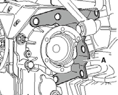
5.38 Support between engine and gearbox
39. Turn the manual transmission through the spindle (At the opposite illustrations) support #3282 in the differential area up and position the manual transmission through the spindle (2) support No. 3282 with an inclination to the left. Then remove the assembly of manual transmission and angular transmission from the flywheel, making sure that it does not touch the side member (arrow). Carefully lower the manual transmission, keeping an eye on its connecting lines.
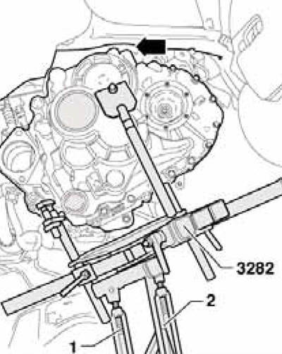
5.39 Removing the manual transmission
40. Clean input shaft splines and lightly lubricate with G000 100 grease. Clutch disc should slide easily over input shaft.
41. Make sure that the centering sleeves of the manual transmission are properly seated on the engine. In the absence of centering sleeves, shifting difficulties, clutch problems and manual transmission noise can occur (off gears). Also make sure the position of the intermediate plate on the motor is correct.
42. Installation is carried out in the reverse order. Use new self-locking bolts and nuts. The tightening forces of the bolts for fastening the manual transmission to the engine, as well as the fastening of the supports, are indicated in Sections "Removal and installation of the engine" Chapters 2.