
Attention! When installing the front suspension arm, you must use a new bolt securing the arm to the beam.
Attention! If the rubber-metal hinge of the lever is damaged, replace the lever assembly with the hinge.
Fastening the lever to the beam of the front suspension
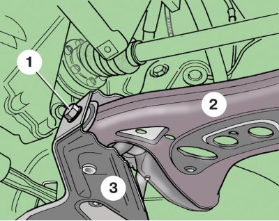
1 - bolt; 2 - lever; 3 - front suspension beam
Removing the front suspension arm
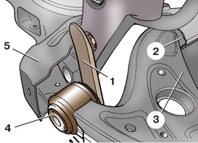
1 - mounting blade; 2 - rubber-metal support; 3 - lever; 4 - rubber-metal hinge; 5 - front suspension beam
1. Loosen bolts 9 (see fig. Front suspension parts) fastening of the corresponding wheel.
2. Unscrew the nut 10 of the hub.
3. Raise and secure the front of the vehicle.
4. Remove the front wheel, finally unscrewing the bolts of its fastening.
5. Mark the position of the bolts 2 (see fig. ball joint mount) fastening the ball joint on the suspension arm 1, circling the contours of the bolt heads. This will help, after assembly, approximately maintain the wheel alignment angles. Turn away bolts 2 fastenings of a spherical support 3 to the lever.
6. With special puller 1 (see fig. Pressing the splined tip of the outer CV joint from the hub) press the splined tip of the outer CV joint from the wheel hub 2. In the absence of a puller, this can be done by hammer blows through a wooden spacer on the end of the splined tip. Suspend the wheel drive to the body with a wire.
7. Sliding rack 2 (see subsection 7.2.3) towards you, install a wooden spacer 1 between it and the body.
8. Remove bolt 1 (see fig. Fastening the lever to the beam of the front suspension) fastening the lever 2 to the beam 3 of the front suspension.
9. Pull out the hinged eye 4 (see fig. Removing the front suspension arm) lever 3 from beam 5 (so as not to damage the rubber-metal support 2) and using a mounting spatula 1, press the lever axle out of the rubber-metal support 2 of the suspension bracket.
10. Lubricate the lever axle 3 with graphite grease.
11. Insert the lever axle into the hexagonal hole of the rubber-metal bearing (see subsection 7.2.5), if necessary, you can use the mounting spatula. Make sure that the axle fits into the hole without any gaps, i.e. does not rotate in it. Otherwise, the hinge must be replaced (see subsection 7.2.6).
12. Screw in a new bolt of fastening of the lever to a beam of a forward suspension bracket.
13. Assemble the front suspension in reverse order. Carving connections of a suspension bracket finally tighten on the car standing on the earth.
Tightening torques, Nm
| wheel hub nut | 30 |
| Bolts of fastening of the spherical hinge to the suspension arm | 20, then turn 90° |
| Bolt of fastening of the lever to a beam of a forward suspension bracket | 70, then tighten by 90° |
| Wheel bolts | 120 |