
Stabilizer pad mounting
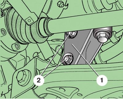
1 - bracket; 2 - bolts
Attaching the rack to the bar of the stabilizer bar
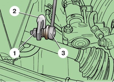
1 - nut; 2 - rod; 3 - rack
Fastening of the steering mechanism to a beam of a forward suspension bracket
1 - bolt; 2 - front suspension beam
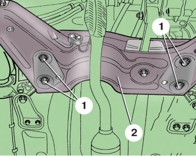
Fastening of a beam of a forward suspension bracket
1, 2, 4 - bolts; 3 - beam; 5 - bracket; 6 - trunnion
Installation of the lever axis in the rubber-metal bearing
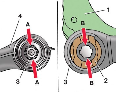
1 – an arm of a beam of a forward suspension bracket; 2 - rubber-metal support; 3 - axis of the lever; 4 - lever; A, B - mating surfaces of the axis of the lever and support
1. Loosen bolts 9 (see fig. Front suspension parts) fastening of the corresponding wheel.
2. Unscrew the nut 10 of the hub.
3. Raise and secure the front of the vehicle.
4. Remove the front wheel, finally unscrewing the bolts of its fastening.
5. Remove the engine crankcase mudguard.
6. Mark the position of the bolts 2 (see fig. ball joint mount) fastening the ball joint on the suspension arm 1, circling the contours of the bolt heads. This will help, after assembly, approximately maintain the wheel alignment angles. Turn away bolts 2 fastenings of a spherical support 3 to the lever.
7. With special puller 1 (see fig. Pressing the splined tip of the outer CV joint from the hub) press the splined tip of the outer CV joint from the wheel hub 2. In the absence of a puller, this can be done by hammer blows through a wooden spacer on the end of the splined tip. Suspend the wheel drive to the body with a wire.
8. Sliding the rack 2 towards you, install a wooden spacer 1 between it and the body.
9. Loosen two screws 2 (see fig. Stabilizer pad mounting) fastening to the bracket 1 clip 5 (see fig. Details of the front suspension beam) anti-roll bar pads.
10. Loosen one nut 1 (see fig. Attaching the rack to the bar of the stabilizer bar) fasteners and disconnect the rack 3 from the bar 2 of the stabilizer on both sides of the suspension.
11. Remove bolts 1 (see fig. Fastening of the steering mechanism to a beam of a forward suspension bracket) fastening the steering mechanism to the beam 2 of the front suspension.
12. Secure the steering gear with wire.
13. Turn away two bolts 3 fastenings of a back support 2 of the power unit to a transmission (see subsection 7.1.2.1).
14. Place a secure support under the front suspension beam.
15. Remove bolt 4 (see fig. Fastening of a beam of a forward suspension bracket) on the left side of the beam. Screw in the centering pin 6 instead (Т10096) and tighten to 20 Nm.
16. Remove bolt 4 on the right side of the beam. Screw in the centering pin 6 instead (Т10096) and tighten to 20 Nm.
17. Remove bolts 1 on both sides.
18. Unscrew bolt 2 on the left side of the beam and remove bracket 5. Instead of bolt 2, screw in centering pin 6.
19. Remove the support and lower the beam approximately 40 mm. At the same time, make sure that the power steering lines are not stretched.
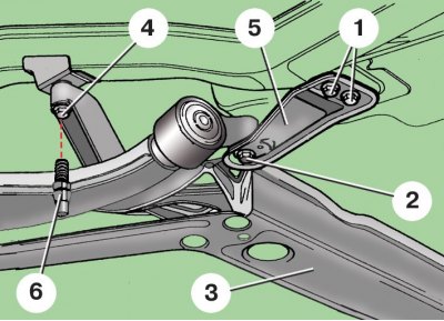
20. Remove bolt 1 (see fig. Fastening the lever to the beam of the front suspension) fastening the lever 2 to the beam 3 of the front suspension.
21. Remove lever 12 (see fig. Details of the front suspension beam) together with bracket 20.
22. Disconnect the lever from the bracket by pressing the lever axis out of the rubber-metal support of the bracket using a puller.
23. Lubricate the lever axle with graphite grease.
24. Clamp the bracket in a vise with soft metal pads on the jaws.
25. Insert manually the axis of the lever into the hexagonal hole of the rubber-metal support of the bracket in accordance with fig. Installation of the lever axis in the rubber-metal support (Surfaces A and B must match). Make sure that the axle fits into the hole without any gaps, i.e. does not rotate in it. Otherwise, the support must be replaced (see subsection 7.2.6).
26. Install the suspension arm with bracket on the vehicle in reverse order, while replacing the suspension mounting bolts with new ones. Bolts 21 and 22 (see fig. Details of the front suspension beam) screw in the following sequence: screw bolt 22 by hand, then bolts 21 by hand, then tighten evenly alternately. Carving connections of a suspension bracket finally tighten on the car standing on the earth. Check and, if necessary, adjust the wheel alignment.
Tightening torques, Nm
| wheel hub nut | 30 |
| Bolts of fastening of the spherical hinge to the suspension arm | 20, then turn 90° |
| Bolts 9 (see fig. Details of the front suspension beam) mounting bracket to body | 20, then turn 90° |
| Bolts 10 (see fig. Details of the front suspension beam) mounting bracket to body | 70, then tighten by 90° |
| Bolts of fastening of a back support to a transmission | 30, then turn 90° |