
Ball joint marking
Letter L - left support, R - right; the number 3 indicates that the support is used on models with wheel size 13", and the number 4 - 14". In addition, the arrow on the support for models with size 14 wheels" indicates the direction of the vehicle.
Ball joint clearance check
Axial clearance check
1. Hang the front wheel.
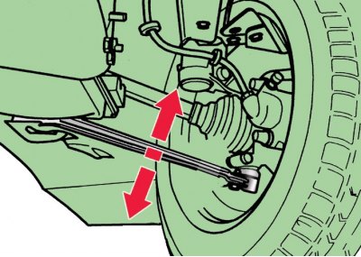
2. To check the axial clearance in the ball joint, swing the lever in the vertical plane in the direction shown by the arrows.
Radial clearance check
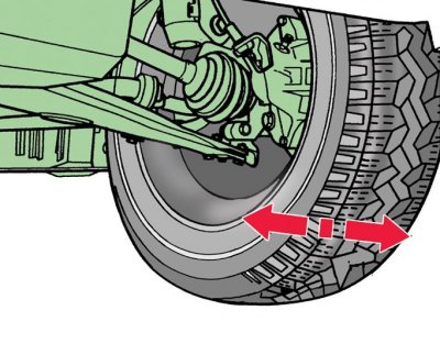
3. To check the radial clearance, shake the wheel by grasping it from above and below in the direction of the arrow.
4. If play is felt in at least one case, the ball joint must be replaced.
Replacement
1. Loosen the wheel bolts and hub nuts.
2. Raise and secure the front of the vehicle.
3. Remove the front wheel, finally unscrewing the bolts of its fastening.
4. Finally loosen the hub nut.
5. Loosen nut 14 (see fig. Details of the front suspension beam) ball joint pin.
6. Mark the position of the bolts 2 (see fig. ball joint mount) fastening the ball joint on the arm 1 of the front suspension, circling the contours of the bolt heads.
7. Turn away bolts 2 fastenings of a spherical support to the lever.
8. With special puller 1 (see fig. Pressing the splined tip of the outer CV joint from the hub) press the splined tip of the outer CV joint from the wheel hub 2. In the absence of a puller, this can be done by hammer blows through a wooden spacer on the end of the splined tip.
9. Suspend the wheel drive to the body with a wire.
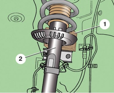
10. Sliding the rack 2 towards you, install a wooden spacer 1 between it and the body.
11. Using a universal puller, press out the ball joint pin 15 (see fig. Details of the front suspension beam) from the steering knuckle.
12. Install the ball bearing on the steering knuckle in accordance with the marking.
13. Screw in the new ball stud nut while holding the stud from turning with a socket wrench.
14. Lubricate the splines of the hub and the splined tip of the outer CV joint with graphite grease.
15. Press the hub onto the wheel drive by screwing in a new hub nut.
16. Attach the ball joint to the suspension arm and secure with new bolts, installing the bolts in accordance with the previously made markings. Do not damage the protective boot of the ball joint.
17. Install the front wheel.
Tightening torques, Nm
| Ball joint pin nut | 20, then turn 90° |
| wheel hub nut | 30 |
| Bolts of fastening of the spherical hinge to the suspension arm | 20, then turn 90° |
| Wheel bolts | 120 |