
Ball joint mount
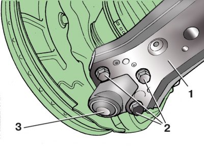
1 – front suspension arm; 2 - bolt; 3 - ball joint
Details of the front suspension strut
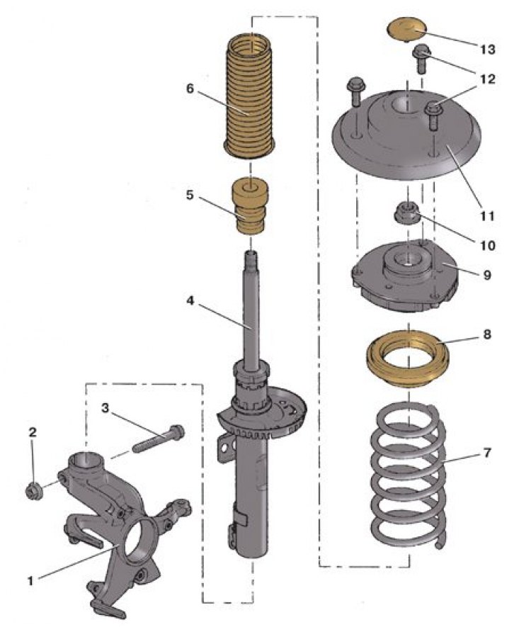
1 – a rotary fist; 2 - nut; 3 - coupling bolt; 4 - shock absorber; 5 – compression buffer; 6 - protective cover; 7 – front suspension spring; 8 - thrust bearing support; 9 – rack support; 10 - rod nut; 11 - support plate; 12 – a bolt of fastening of a rack; 13 - protective cap
Details of the front suspension beam

1 - beam; 2 – a nut of fastening of a rack to a bar of the stabilizer; 3 – stabilizer bar; 4 - rod cushion; 5 - cushion holder; 6 – a nut of fastening of a stabilizer rack to a telescopic rack; 7 – a rack of the stabilizer of cross stability; 8 - bracket; 9, 10, 19, 22 - bolts; 11 - rubber-metal support; 12 – front suspension arm; 13 - locking plate; 14 – nut of a finger of a spherical support; 15 - ball bearing; 16 – a bolt of fastening of a spherical support; 17 - air duct; 18 - caps; 20 - beam bracket; 21 – a bolt of fastening of the steering mechanism; 23 - bolts for fastening the rear support of the power unit to the gearbox; 24 – a bolt of fastening of a back support of the power unit to a beam; 25 - rear support of the power unit
1. Loosen bolts 9 (see fig. Front suspension parts) fastening the corresponding wheel and nut 10 of the hub.
2. Raise and secure the front of the vehicle.
3. Remove the front wheel, finally unscrewing the bolts of its fastening.
4. Unscrew the fastening nut 26 and disconnect the anti-roll bar 27 from the telescopic strut 1.
5. Disconnect the wires from the wheel speed sensor 24. Turn away a bolt 25 of fastening and remove the gauge 24 of frequency of rotation of a wheel.
6. Remove caliper 13 and hang it on a wire to the body (see subsection 9.5.1) or (see subsection 9.6.1).
7. Mark the position of the bolts 2 (see fig. ball joint mount) fastening the ball joint on the suspension arm 1, circling the contours of the bolt heads. This will help, after assembly, approximately maintain the wheel alignment angles.
8. Turn away bolts 2 fastenings of a spherical support 3 to the lever.
9. With special puller 1 (see fig. Pressing the splined tip of the outer CV joint from the hub) press the splined tip of the outer CV joint from the wheel hub 2. In the absence of a puller, this can be done by hammer blows through a wooden spacer on the end of the splined tip.
10. Hang the wheel drive to the body with a wire.
11. Disconnect the tie rod from the steering knuckle (see subsection 8.4.1) and hang it on a wire to the body.
12. In the engine compartment, unscrew the three bolts 12 (see fig. Details of the front suspension strut) attaching the strut to the body and remove the strut through the wheel well.
13. Install the telescopic strut in the reverse order, replacing the nuts of the hub and ball pin of the tie rod end, as well as bolts 16 (see fig. Details of the front suspension beam) fasteners of the ball joint and their locking plate 13. First of all, screw in the bolts 12 (see fig. Details of the front suspension strut) rack mounts on the side of the engine compartment.
Tightening torques, Nm
| wheel hub nut | 30 |
| Bolts of fastening of the spherical hinge to the suspension arm | 20, then turn 90° |
| Nut of a spherical finger of a tip of steering draft | 20, then turn 90° |
| Nut of fastening of a rack of the stabilizer of cross-section stability to a forward rack | 40 |
| Bolts of the top fastening of a forward rack | 25 |
| Bolt of fastening of the sensor of frequency of rotation of a wheel | 8 |
| Wheel bolts | 120 |