
Understeering's shifter
Removing the steering column switch
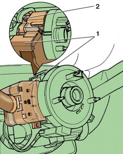
1 - steering column switch; 2 - coupling bolt
Steering column adjustment
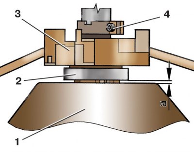
1 – a steering wheel; 2 - return ring; 3 - steering column switch; 4 - coupling bolt
1. Disconnect the wire from the terminal «-» battery.
2. Remove the steering wheel (see subsection 8.1).
3. Remove return and slip rings (see subsection 8.2).
4. Disconnect the two pads with wires from the steering column switch 1 (see fig. Removing the steering column switch).
5. Loosen pinch bolt 2.
6. Remove the steering switch from the steering column.
7. Install the switch on the steering column, without tightening the coupling bolt, and connect the blocks with wires to it.
8. Install return and slip rings and steering wheel.
9. Align the switch horizontally.
10. Adjust the switch position so that the dimension a (see fig. Steering column adjustment) was 2.5 mm, and tighten the tie bolt 4.
11. Install the steering column covers.
Switches on the instrument panel
Removing the switch on the instrument panel
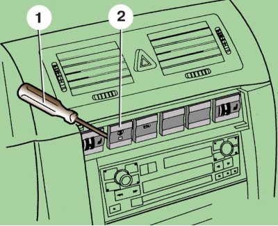
1 - screwdriver; 2 - switch
1. Disconnect the wire from the terminal «-» battery.
2. Gently pry with a screwdriver 1 (see fig. Removing the switch on the instrument panel) on the left side, remove switch 2 from the instrument panel.
3. Disconnect the wiring harness from the switch.
4. When installing the switch, push it in until it locks into place in the instrument panel.
Hazard switch
Removing the Hazard Switch
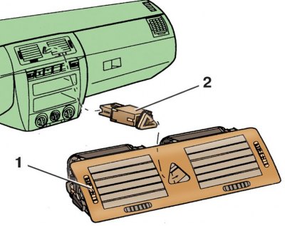
1 - central nozzles; 2 - switch
1. Disconnect the wire from the terminal «-» battery.
2. Remove the central nozzles from the instrument panel (see subsection 11.8).
3. Pull out switch 2 (see fig. Removing the Hazard Switch) from the central nozzles 1.
4. Install the switch in reverse order.
Power mirror switch
Removal and installation of the switch of the electric drive of external mirrors
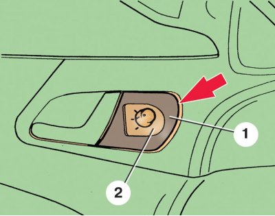
1 - decorative overlay; 2 - switch
1. Disconnect the wire from the terminal «-» battery.
2. Using a screwdriver, remove trim 1 (see fig. Removal and installation of the switch of the electric drive of external mirrors) along with switch 2.
3. Disconnect the wiring harness from the switch.
4. Opening the latches, remove the switch from the decorative trim.
5. Install the switch in reverse order.
Side console
Removing the side console
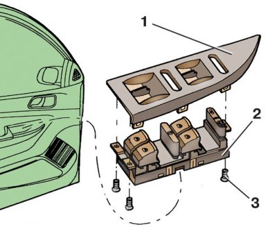
1 - decorative overlay; 2 - side console with switches; 3 - screws
1. Disconnect the wire from the terminal «-» battery.
2. Using a screwdriver, remove trim 1 (see fig. Removing the side console) along with side console 2.
3. Disconnect the block with wires from the side console 2.
4. Unscrew the screws 3 and remove the decorative trim 1 from the side console 2.
5. Install the side console in reverse order.
Central light switch panel
Removing the central light switch panel
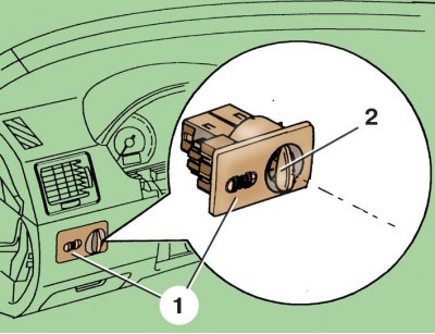
1 - panel; 2 - handle of the central light switch
Removing the block of switches of the corrector of headlights and illumination of devices
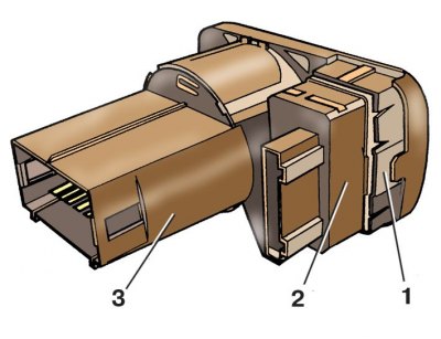
1 - latch; 2 - block of switches; 3 - central light switch
1. Disconnect the wire from the terminal «-» battery.
2. Install handle 2 (see fig. Removing the central light switch panel) into position «0».
3. Dip handle 2, turn it to the vertical position and pull out the panel with switches.
4. Disconnect two pads with wires.
5. To remove block 2 (see fig. Removing the block of switches of the corrector of headlights and illumination of devices) headlight range control and instrument illumination switches, press the plastic latch 1.
6. Install the central switch panel in reverse order.