
Temperature-sensitive sensor-switch of the fan of the cooling system
General information
A temperature-sensitive sensor-switch turns on the fan when the coolant temperature reaches 95÷99°C. Opening of the contacts of the sensor-switch occurs when the temperature drops to a value of at least 88°C.
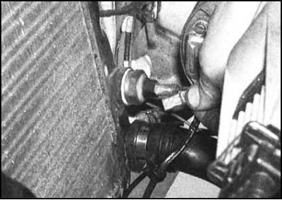
The sensor-switch is screwed into the right side radiator tank. The tightness of the connection is achieved by installing an aluminum sealing washer. The upper part of the sensor-switch housing is equipped with flats for a 27 mm wrench.
On the body of the sensor-switch there are two outputs for connecting the electrical wiring. Power is supplied to the sensor only when the ignition is on. Circuit protection provided by fuse No. 4 (15 A).
Examination
A detailed description of the sensor-switch test is given in Section Check of serviceability of functioning, removal, installation, dismantling and assembly of the fan of the cooling system as part of the fan check procedures.
Removing
Note. Wait for the engine and radiator to cool completely before removing the sensor-switch.
1. The sensor-switch is screwed into the body of the radiator.
2. Disconnect the negative cable from the battery, then drain the coolant, lowering its level below the level of the sensor-switch. Alternatively, prepare a suitable plug that can quickly plug the hole for installing the sensor-switch. Take care not to damage the radiator and keep debris and foreign objects from entering the system.
3. Disconnect the wiring from the sensor-switch.
4. Carefully turn out the gauge switch and remove it from a radiator. Also remove the sealing washer. If the coolant has not drained, plug the hole with a prepared plug without delay.
Installation
1. Installation is carried out in the reverse order. Don't forget to replace the sealing washer. Tighten the sensor-switch with the required force, then add the required amount of coolant to the system.
2. Finally, start the engine and warm it up to normal operating temperature. make sure that the fan is working properly - it should turn on and off in a timely manner.
Coolant temperature sensor (CTS)
Examination
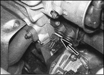
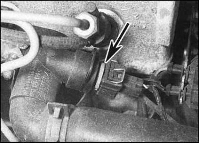
1. On petrol models, the CTS is installed in the thermostat housing on the left side of the cylinder head.
2. On diesel models, the sensor is located in the outlet pipe of the cooling path at the front of the head.
Note. On 1.3L models equipped with a central injection system (SPFI), the sensor is only connected to the temperature meter. on all other models CTS is also used to determine the temperature of fuel injection systems (gasoline engines) or preheat (diesel engines).
3. Stabilized supply voltage to the temperature meter from the instrument panel (through the ignition switch and fuse). The state of the meter's ground loop is monitored by the CTS. The main component of the CTS is the thermistor, a resistor whose resistance decreases with increasing temperature. When the coolant is cold, the resistance of the thermistor is high and a small current passes through the meter, while the pointer is in the lower range of the scale (blue sector). As the engine warms up, the resistance of the sensor drops, the current increases and the arrow moves upwards, approaching the red sector of the scale. A defective CTS must be replaced.
4. In case of failure of the CTS, first of all, you should check the correct operation of the other components of the instrument cluster - if they are completely de-energized, check for power on the shield. If the readings of the meters are unstable, the voltage stabilizer built into the printed circuit board of the instrument panel may be faulty, which must be replaced (see chapter Onboard electrical equipment). If only the temperature meter fails, perform the checks in the following paragraphs.
5. If the meter needle remains within the blue sector of the scale when the engine is warm, disconnect the electrical wiring from the CTS and ground the corresponding wire to the mass of the cylinder head. If the arrow deviates when the ignition is turned on, the sensor is faulty and must be replaced. If no change in meter behavior occurs, remove instrument cluster (see chapter Onboard electrical equipment) and check for continuity in the section of circuit between the sensor and the meter. If there is continuity, then the meter is defective and must be replaced.
6. If the meter needle is constantly in the red range of the scale, not reacting in any way to the cooling of the engine, disconnect the electrical wiring from the sensor. If the needle returns to the top of the scale when the ignition is turned on, replace the CTS. Otherwise, check the rest of the chain.
Removing
Note. Allow the engine and radiator to cool completely before removing the CTS.
1. Partially drain the coolant (below the level of the CTS location), or prepare a suitable plug.
2. Disconnect wiring from CTS. Now you should determine the type of sensor installed on your car. The sensor can have either a loose fit or a threaded fit.
3. The threaded sensor is simply screwed out of the engine. Don't forget to remove the sealing washer.
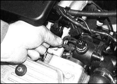
4. The loose fit sensor is fixed with a special clip, which must first be removed.
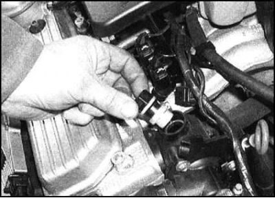
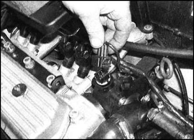
5. Then the sensor is simply removed from its socket.
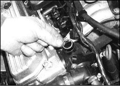
6. Finally, also remove the O-ring.
Installation
1. On a screw-fit sensor, replace the sealing washer, then screw the sensor into place and tighten securely.
2. For a loose-fit sensor, install a new O-ring onto the sensor, then push the assembly into the seat and secure it with the clip.
3. Connect the electrical wiring, then add the required amount of coolant to the system.
Fuel Injection System Temperature Sensor (petrol models)
Examination
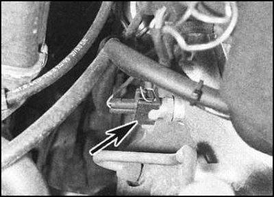
1. On 1.3L models with central fuel injection (SPFI) the temperature sensor is screwed into the rear of the intake manifold. On all other engines, the sensor is combined with the CTS and installed in the thermostat housing at the left end of the cylinder head.
2. The sensor is a thermistor. Electronic control unit (ECU) The engine/fuel injection control system supplies the sensor with a supply voltage and measures the current flowing in the working circuit of the sensor, the value of which is determined by the temperature of the thermistor. The information received is then used, among other input signals, to determine the moment and duration of the injectors, setting the idle speed, etc.
3. When the sensor circuit malfunctions, the ECU starts to ignore the signal generated by the thermistor, using instead some effective average value that ensures the adequate functioning of the systems under control. At the same time, a warning lamp on the instrument panel turns on, warning the owner of the vehicle about the need to contact a service station. Checking the state of the sensor itself is possible only with the use of a proprietary diagnostic reader from Skoda. To avoid the risk of damage to the ECU, no attempt should be made to understand the situation using any other means at hand.
Preheat system temperature sensor (diesel models)
Examination
A detailed description of the procedure for checking the correct functioning of the preheating system of a diesel engine is given in Part Preheating system for diesel engines Heads Electric equipment of the engine.
Removal and installation
The sensor is integrated into a single unit with the CTS and is installed in the outlet pipe of the cooling path, located in front of the cylinder head. The description of the procedures for removing and installing the sensor is given above.