
Removing
Note: The engine is removed downwards with the DSG.
1. Remove the battery (see chapter 5).
2. Loosen the front right wheel hub bolt no more than 90°.
3. Remove the front wheels and front wheel arch lockers.
4. Remove the front right drive shaft (see chapter 8).
5. Separate the left drive shaft (1 per resist. illustrations) from flange shaft DSG (see chapter 8). Give a nut of the left stabilizer link (2) and separate it from the stabilizer. Then give three nuts (3) left ball joint and squeeze it out of the suspension arm.
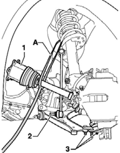
5.5 Fixing the left drive shaft to the suspension strut
6. If there is a suspension height sensor, give the nut (2 to resist. illustrations) its fastening to the lever. Turn the steering wheel all the way to the left, pull the ball joint outward and use a suitable belt to (And in illustration 5.5) fasten the left drive shaft to the suspension strut so that the CV joint does not kink too much. Insert a pin into the suspension arm to stabilize the ball joint.
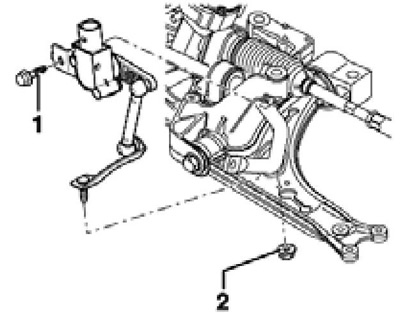
5.6 Nut (2) suspension level sensor mounts
7. Remove the air cleaner along with the hose going to the throttle module (see chapter 4). Remove the bolts (see resist. illustration) and remove the air cleaner bracket.
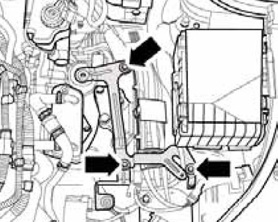
5.7 Fixing the air cleaner bracket
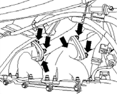
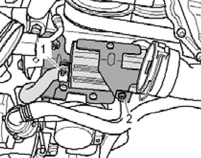
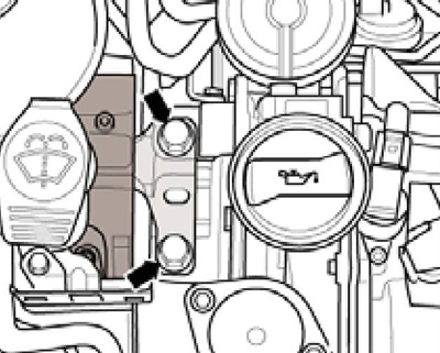
8. Remove the upper part of the inlet pipeline (see chapter 4). Give fasteners (arrows on resist. illustrations) coolant pipes to the casing, and then remove the bolts (1) and remove the cover together with the intake manifold support.
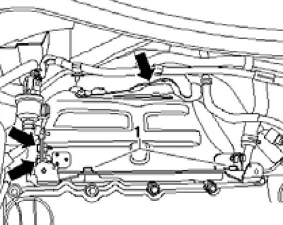
5.8 Fixing the coolant pipe (arrows) and bolts (1) casing
9. Give nuts of fastening of an exhaust pipe to final collectors (see resist. illustration) and move it back slightly.
5.9 Fastening the exhaust pipe to the manifolds
Note: Do not allow flexible sections to be bent more than 20°to avoid damaging them.
10. Remove the accessory drive belt (see Section 6). To do this, first completely remove the EVAP adsorber with the purge solenoid valve (see chapter 4).
11. Loosen the oscillator fasteners in sequence (1-3 per resist. illustrations) and take it off.
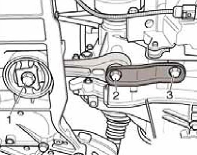
5.11 Fixing the oscillating support
12. Remove fan shroud "V7" And "V35" radiator, bleed the coolant and remove the lower radiator support (see chapter 3).
13. Disconnect the connector (1 in illustration 5.13a) magnetic clutch of the compressor and remove the bolts (arrows). Remove the climate system compressor without disconnecting the refrigerant lines from it, and secure it to the hood lock holder with a wire (And in illustration 5.13b) so that the refrigerant lines are not stretched or kinked.
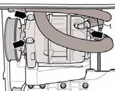
5.13a Connector (1) and fasteners (arrows) refrigeration compressor
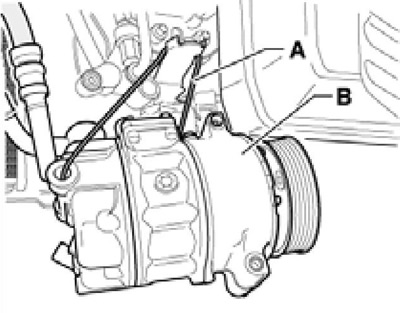
5.13b Fixing the compressor
14. On models with an additional heater, loosen the clamp (1 per resist. illustrations), remove the bolt (2) and remove the auxiliary heater exhaust pipe. Disconnect the existing lines on the coolant pipe and on the shut-off valve "N279" heating systems.
5.14 Removing the auxiliary heater exhaust pipe
15. Give fasteners of the flexible disk of the cardan shaft to the DSG (see chapter 8).
16. Disconnect the connector (1 per resist. illustrations) sensor "G266" engine oil level and temperature. Remove bracket (2) the electrical wiring of the G266 sensor from the support of the power unit.
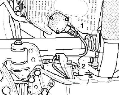
5.16 Wiring G266
17. Disconnect the coolant lines from the radiator, expansion tank and heater core (see chapter 3).
18. Remove the selector lever cable from the DSG (see chapter 7).
19. Press on the retaining ring and separate the fuel supply line (2 to resist. illustrations).
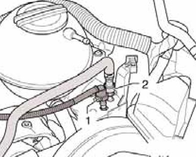
5.19 Fuel supply line (2) and ventilation line (1)
20. Disconnect the engine wiring harness connector from the ECM (front connector).
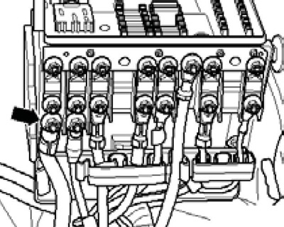
21. Release the guide plate (2 to resist. illustrations) wiring harness and pull it up. Cut the ties (4), Remove the bolts (3) on the wall (1) air intake chamber. Lift the left side of the wall and pull out the wiring harness.
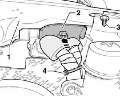
5.21 Releasing the wiring harness
22. Give the nut (see resist. illustration) and disconnect the generator wire from the mounting block.
5.22 Generator wire on mounting block
23. Open the entire engine wiring harness protection on the side member (see resist. illustration). Open other connections of the engine wiring harness, remove it, lay it on the engine and secure with clamps.
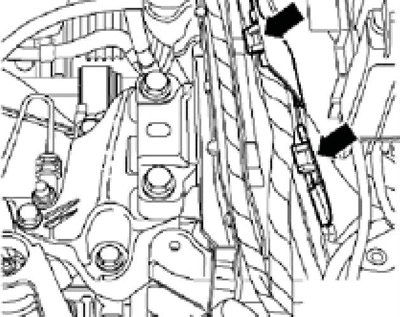
5.23 Wire harness protection
24. Remove the protective cap and disconnect the wire (1 per resist. illustrations) from the e / m starter valve. Disconnect connector (2) on the solenoid valve and disconnect the ground wire (3) from the DSG console. Discharge yourself from electrostatic charge by touching the body ground with your bare hand, and then turn the DSG connector stopper (4) and disconnect it.
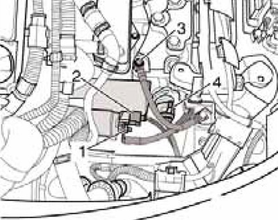
5.24 Starter wiring
25. Disconnect/disengage any other interfering engine and transmission wiring. Remove the vacuum line from the brake booster.
26. Install the T40074 engine support on the VAG1383A transmission jack, remove the T40074 / 1 adapter from it and fix this adapter on the cylinder block with a nut (1 per resist. illustrations). Then lift the support and attach the adapter to it again (2).
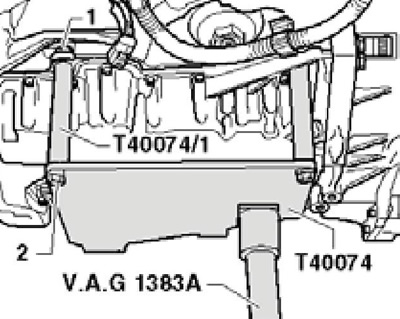
5.26 Support T40074 on the transmission jack
27. Fix the T40074 support to the exhaust side of the cylinder block by tightening the bolts (arrows on resist. illustrations) with a force of 20 Nm. Raise the power unit slightly on the transmission jack. Make sure all hoses, pipes and wires between engine, DSG and body are disconnected.
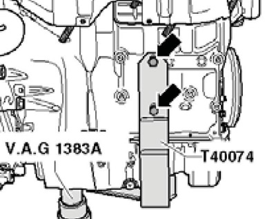
5.27 Fastening support T40074 on the exhaust side of the cylinder block
28. From the ladder, loosen the bracket bolts on the engine (see illustration 5.28a), and then - the bracket bolts on the DSG (2 in illustration 5.28b). Together with an assistant, pull the power unit forward as far as possible, and then lower it on a jack, being careful not to damage the power unit and parts of the engine compartment. Guide the power unit if necessary. Separate the transmission from the engine (see chapter 7) and attach it to the mounting stand.
5.28a Bracket bolts on the engine
5.28b Bracket bolts on DSG
Installation
Note: Lay hoses and electrical wiring in the same way as they were located before removal; Install all clamps and ties in their original places. Fasteners, depending on the thread, tighten with the following forces: M6 - 9 Nm, M7 - 13 Nm, M8 - 20 Nm, M10 - 40 Nm, M12 - 70 Nm.
29. Before installation, the needle bearing of the crankshaft should be replaced (see Section 14).
30. Installation is carried out in the reverse order. Pay attention to the following features.
31. Use new self-locking nuts and bolts that need to be tightened to a certain angle. Use new seals and gaskets.
32. Make sure that the centering sleeves for the transmission are inserted into the cylinder block. Attach the transmission to the engine (see Chapter 6 or 7).
33. Fix the power unit on the transmission jack, drive it into the engine compartment and screw in the new bolts of the power unit brackets by hand. Adjust the brackets and tighten their mounting bolts (see subsection below).
34. Fix the cardan shaft (see chapter 8), install the oscillator (see subsection below) and drive shafts (see chapter 8).
35. Install the refrigeration compressor and accessory drive belt.
36. Attach the selector cable to the DSG.
37. Lay the engine wiring harness, dock it with the ECM.
38. Install the exhaust pipe.
39. Connect the battery wiring.
40. Check and, if necessary, correct the level of impellent oil.
41. Fill the engine cooling system (see chapter 3).
42. Clear the ECM memory of any DTCs that occurred during removal/installation of the engine and verify that the ECM has generated a readiness code.
43. Do a road test (see chapter 1) and fix any errors you find.
Checking and adjusting the power unit supports
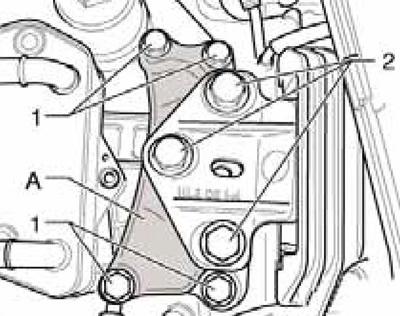
44. Details of the fastening of the supports are indicated on the resist. illustrations.
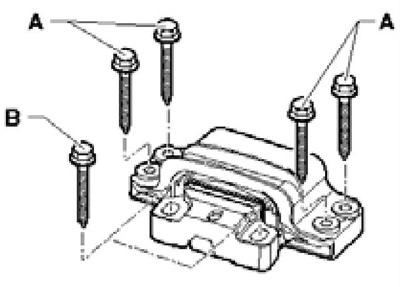
5.44a Bolts of fastening of an arm of the engine, are subject to replacement
A 20 Nm, then tighten to 90°
At 40 Nm, then tighten to 90°
With 60 Nm, then tighten to 90°
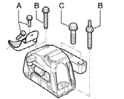
5.44b DSG bracket bolts to be replaced
A 40 Nm, then tighten to 90°
At 60 Nm, then tighten to 90°
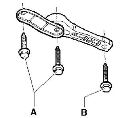
5.44c Oscillating support bolts to be replaced
A 40 Nm (class 8.8) or 50 Nm (class 10.9), then tighten to 90°
At 100 Nm, then tighten to 90°
45. To check the installation of the bracket, measure the distance (and on the opposite illustrations) between the bracket and the support - it should be 10-13 mm. Cast support edge (2) must be parallel to the support arm (1), i.e. distance (X) should be the same front and back. If the engine or transmission hits the side member while cornering and the distance (A) is not 10-13 mm, adjust the bracket as described below.
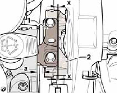
5.45 Checking the installation of the right bracket
46. Remove the air cleaner along with the hose going to the throttle module (see chapter 4). Remove the bolts (see illustration 5.7) and remove the air cleaner bracket.
47. Remove the front hood buffers from the upper sides of both front fenders. Insert plates T10311 on the right (And on the opposite illustrations) and left (IN) sides in the direction of the arrows as far as it will go so that the arrows "R" And "L" on the plates pointed back. These plates are needed in order not to damage the wings.
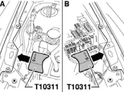
5.47 Installing the protective plates
48. Install support MP9-200 with adapters MP9-200/3 and MP9-200/18 (see resist. illustration). The heel of the support must rest against the buffers (1) and located on top of the side beam (2). Unload the power unit mounts evenly by rotating both spindles.
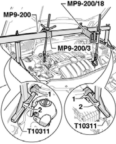
5.48 Unloading power unit supports
49. Loosen the bolts (arrows in illustration 5.28a) fixing the right bracket and slightly (less than 1 turn) loosen the bolts (2 in illustration 5.28b) left bracket mounting.
50. If, when installing the engine, the bracket bolts have not yet been replaced, screw in new bolts one by one.
51. Move the power unit using the lever installed between the support arm (1 in Figure 5.45) and support (2), to distance (A) was 10 mm, and the distance (X) was the same front and back. Tighten the bracket bolts (see illustrations 5.44a-b).
52. Install the remaining parts.