



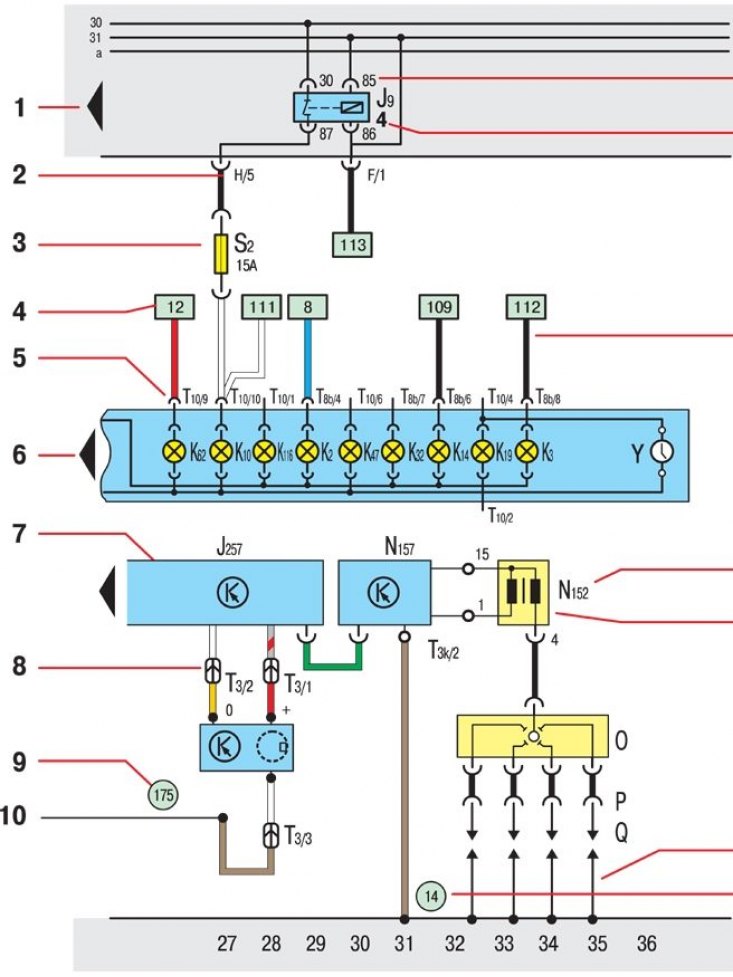
1 – the arrow points to the next electrical circuit included in the electrical equipment schematic diagram;
2 – designation of the plug connector on the relay panel. Indicates the loading of the multi-pin plug connector with a wire, e.g., X/5 – multi-pin plug connector X, contact 5;
3 – fuse designation, eg fuse N₂ (15A) in the fuse box;
4 – a reference to the further passage of the wire. The number enclosed in a frame indicates the electrical circuit in which the continuation of this wire is located;
5 – designation of the plug connector on the part (design node). Contains the marking of the multi-pin plug connector, the number of contacts and the number of the occupied contact, e.g. T10/9 – multi-pin plug connector T10, 10-pin, contact 9;
6 – the arrow indicates the continuation of this part in the next electrical circuit diagram;
7 – detail sign;
8 – designation of the plug connector in the wiring harness. Contains the marking of the multi-pin plug connector, the number of contacts and the number of the occupied contact, e.g. T3/2 – multi-pin plug connector T3, 3-pin, contact 2;
9 – designation of the connection in the wire harness;
10 – a link to further passage of the internal connection. The number indicates the next part of the connection diagram, in which the continuation of this connection is located;
11 – connection designation – relay on the relay panel. Designates individual relay contacts, e.g. 85 – plug contact 85 on the relay;
12 – designation of the place for the relay.
Specifies the location for the relay on the relay panel;
13 – cross-section (in mm²) and color of the wire;
14 – designation of the design unit (part);
15 – designation of the connecting terminal with the marking of the plug contact, which is located on the multi-pin plug connector or, respectively, on the original part;
16 – internal connection (thin line). This connection does not exist as a wire, however, the internal connections are electrically conductive. They allow you to observe the flow of current both inside the parts and inside the wire harnesses;
17 – designation of the ground connection point
(Information presented on the website: skodabook.ru)