



Gasoline engine repair 1.4 liter car Skoda Octavia 3


Removal the engine
Note: The engine is removed together with the gearbox downwards. When reassembling, restore all cable ties to their original locations. Remove both front wheels. Remove the noise-insulating casing. Remove both front...
Note: The engine is removed together with the gearbox downwards. When reassembling, restore all cable ties to their original locations. Remove both front wheels. Remove the noise-insulating casing. Remove both front...

Engine installation
Installation in reverse order. Note: Replace the screws that are tightened by turning the specified angle. Replace the self-locking nuts, as well as the lip seals, O-rings and gaskets. Use clamps identical to those...
Installation in reverse order. Note: Replace the screws that are tightened by turning the specified angle. Replace the self-locking nuts, as well as the lip seals, O-rings and gaskets. Use clamps identical to those...

Removal and installation of engine and gearbox mounts
Removal and installation engine mounts Disconnect the "1" connector. Remove the hose "2" from the adsorber. Remove the retainers with an arrow screwdriver and set the expansion tank of the cooling system aside. Remove...
Removal and installation engine mounts Disconnect the "1" connector. Remove the hose "2" from the adsorber. Remove the retainers with an arrow screwdriver and set the expansion tank of the cooling system aside. Remove...

Details and units of toothed belt transmission
1. Timing belt: Before removing, mark the direction of the belt with chalk or a felt-tip pen; check for wear 2. 25 Nm 3. Tension roller: when removing and installing, remove the engine support bracket 47 Nm 5. Filler...
1. Timing belt: Before removing, mark the direction of the belt with chalk or a felt-tip pen; check for wear 2. 25 Nm 3. Tension roller: when removing and installing, remove the engine support bracket 47 Nm 5. Filler...

Removal the timing belt from the camshaft
Loosen clamps -1, 2- and remove the air duct. Unlock the "arrow" clamps using the "T10527" puller and remove the air duct. Press the release buttons and disconnect the hose "1". Unscrew the screws "arrows" and remove...
Loosen clamps -1, 2- and remove the air duct. Unlock the "arrow" clamps using the "T10527" puller and remove the air duct. Press the release buttons and disconnect the hose "1". Unscrew the screws "arrows" and remove...

Timing Belt Installation/Adjustment
Note: Replace the screws that are tightened to the specified angle. If the sealing ring of the threaded plug is damaged, replace the sealing ring. Check the TDC position of the camshaft and crankshaft: The camshaft...
Note: Replace the screws that are tightened to the specified angle. If the sealing ring of the threaded plug is damaged, replace the sealing ring. Check the TDC position of the camshaft and crankshaft: The camshaft...

Checking the valve timing
Turn the crankshaft 2 revolutions in the direction of engine rotation. Screw the locking bolt "T10340" into the cylinder block until it stops and tighten to a torque of 30 Nm. Turn the crankshaft in the direction of...
Turn the crankshaft 2 revolutions in the direction of engine rotation. Screw the locking bolt "T10340" into the cylinder block until it stops and tighten to a torque of 30 Nm. Turn the crankshaft in the direction of...

Pulley Side Flange Seal — General Installation Diagram
1. 150 Nm and turn 180° (½ turn): replace; when loosening and tightening, use the stop "T10475" 2. Poly V-belt pulley: with torsional vibration damper 3. Sealing ring; for crankshaft on pulley side; do not lubricate 4....
1. 150 Nm and turn 180° (½ turn): replace; when loosening and tightening, use the stop "T10475" 2. Poly V-belt pulley: with torsional vibration damper 3. Sealing ring; for crankshaft on pulley side; do not lubricate 4....

Crankshaft cover pulley side — torque and tightening sequence
Note: Replace screws that are tightened to the specified angle. Tighten the screws in stages.
Note: Replace screws that are tightened to the specified angle. Tighten the screws in stages.

Removal and installation the flywheel
The gearbox has been removed. On vehicles with a manual transmission, remove the clutch. The engine is installed Insert the counter support -MP1-223 (3067)- into the hole in the cylinder block. Counter support...
The gearbox has been removed. On vehicles with a manual transmission, remove the clutch. The engine is installed Insert the counter support -MP1-223 (3067)- into the hole in the cylinder block. Counter support...

Removal and installation of valve timing regulators and valve timing regulator valves
Valve 1 of the valve timing regulator "N₂05" Disconnect connector "1". Unscrew screw "2" and remove valve 1 of the valve timing regulator "N₂05". Valve 1 of the exhaust valve timing regulator "N318" Disconnect connector...
Valve 1 of the valve timing regulator "N₂05" Disconnect connector "1". Unscrew screw "2" and remove valve 1 of the valve timing regulator "N₂05". Valve 1 of the exhaust valve timing regulator "N318" Disconnect connector...

Removal and installation the intake camshaft seal on the pulley side
Remove the timing belt from the camshafts. Unscrew bolt "2" and remove the camshaft gear. Remove the sealing ring using "1" from the "T20143/1" extraction hook. Installation Note: Do not lubricate the new lip seal. Push...
Remove the timing belt from the camshafts. Unscrew bolt "2" and remove the camshaft gear. Remove the sealing ring using "1" from the "T20143/1" extraction hook. Installation Note: Do not lubricate the new lip seal. Push...
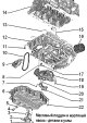
Oil pan and oil pump — parts and components
Note: If a large amount of metal shavings or wear marks are found in the engine during repair, this may be due to damage to the crankshaft and connecting rod bearings. To prevent further damage, the following work must...
Note: If a large amount of metal shavings or wear marks are found in the engine during repair, this may be due to damage to the crankshaft and connecting rod bearings. To prevent further damage, the following work must...

Removal and installation the oil level and temperature sensor «G266»
Drain the oil from the engine. Disconnect connector "3". Unscrew nuts "1" and remove the oil level and temperature sensor "G266" "4". Installation Installation in reverse order. Note: Replace sealing ring "2". Fill the...
Drain the oil from the engine. Disconnect connector "3". Unscrew nuts "1" and remove the oil level and temperature sensor "G266" "4". Installation Installation in reverse order. Note: Replace sealing ring "2". Fill the...

Removal and installation the lower part of the oil pan
Drain the oil from the engine. Disconnect connector "1" of the oil level and temperature sensor "G266". Loosen in sequence -19...1- and completely unscrew the screws. At the point marked with an "arrow", carefully pry...
Drain the oil from the engine. Disconnect connector "1" of the oil level and temperature sensor "G266". Loosen in sequence -19...1- and completely unscrew the screws. At the point marked with an "arrow", carefully pry...

Removal and installation the oil pump
Remove the lower part of the oil pan. Remove the cover of the oil pump drive chain "arrows". Screw in the "arrow" screws. Remove the oil pump with the drive gear from the drive chain. Installation Check that the...
Remove the lower part of the oil pan. Remove the cover of the oil pump drive chain "arrows". Screw in the "arrow" screws. Remove the oil pump with the drive gear from the drive chain. Installation Check that the...

Removal and installation the upper part of the oil pan
Remove the air conditioning compressor from the bracket and tie it up. Remove the oil pump. Loosen in sequence -19...1- and completely unscrew the screws. Carefully separate the upper part of the oil pan from the gluing...
Remove the air conditioning compressor from the bracket and tie it up. Remove the oil pump. Loosen in sequence -19...1- and completely unscrew the screws. Carefully separate the upper part of the oil pan from the gluing...

Oil filter and oil pressure sensor — parts and components
1. Oil filter, 20 Nm: remove and install with oil filter wrench "3417"; before installation, lightly lubricate the sealing ring with clean engine oil 2. Low oil pressure sensor "F378", 20 Nm: response pressure 0.3...0.6...
1. Oil filter, 20 Nm: remove and install with oil filter wrench "3417"; before installation, lightly lubricate the sealing ring with clean engine oil 2. Low oil pressure sensor "F378", 20 Nm: response pressure 0.3...0.6...

Oil sensors and valves
Removal and installation the oil pressure sensor "F22" Note: When installing, secure all thermal insulation cuffs in their original places. Remove the noise-insulating casing. Unscrew the "arrow" bolts and remove the...
Removal and installation the oil pressure sensor "F22" Note: When installing, secure all thermal insulation cuffs in their original places. Remove the noise-insulating casing. Unscrew the "arrow" bolts and remove the...

Removal and installation the toothed pulley of the coolant pump drive
Remove the coolant pump. Loosen bolt "1" using stop "T10172" with adapters "T10172/2". Unscrew the bolt and remove toothed pulley "2". Installation Installation in reverse order. Install the toothed pulley. The notches...
Remove the coolant pump. Loosen bolt "1" using stop "T10172" with adapters "T10172/2". Unscrew the bolt and remove toothed pulley "2". Installation Installation in reverse order. Install the toothed pulley. The notches...

Radiators and fans — parts and components
1. Radiator of the cooling system; after replacement, change the coolant 2. Coolant hose: to remove, lift the mounting bracket 3. Mounting bracket 4. Sealing ring; replace 5. Coolant temperature sensor at the radiator...
1. Radiator of the cooling system; after replacement, change the coolant 2. Coolant hose: to remove, lift the mounting bracket 3. Mounting bracket 4. Sealing ring; replace 5. Coolant temperature sensor at the radiator...

Removal and installation the intake manifold
Remove the air filter housing. Remove the noise-insulating casing. Warning! Risk of injury from fuel jet. To relieve fuel pressure before opening the fuel system, wrap the connection with a clean rag and carefully...
Remove the air filter housing. Remove the noise-insulating casing. Warning! Risk of injury from fuel jet. To relieve fuel pressure before opening the fuel system, wrap the connection with a clean rag and carefully...
This section is available on russian, bulgarian, belarusian, ukrainian, serbian, croatian, romanian, polish, slovak, hungarian
Read similar sections on other Skoda models
➧ Diesel engines 1.9 l: Engine repair Skoda Fabia 2 (2007-2014)
➧ Power unit: Engine in car Skoda Favorit (1987-1994)
Link to this section in various formats
TEXTHTMLBB Code
- General information
- User manual
- Car driving
- Maintenance
- Petrol engines 1.2 l
- Engine repair
- Cooling system
- Supply system
- Petrol engines 1.4 l
- Engine repair
- Supply system
- Petrol engines 1.8/2.0 l
- Engine repair
- Cooling system
- Supply system
- Diesel engines 1.6/2.0 l
- Engine repair
- Cooling system
- Supply system
- Transmission
- Mechanical gearbox 02S
- Automatic gearbox 0CW
- Automatic gearbox 0D9
- Chassis (running gear)
- Front suspension
- Rear suspension
- Brake system
- Steering
- Body and interior
- Doors, locks and windows
- Exterior (external elements)
- Interior (internal elements)
- Ventilation and air conditioning
- Electrical equipment
- Equipment and devices
- Headlights and lighting
- Wiring diagrams (basic)
- Wiring diagrams (comfort)
- General information
- Vehicle details
- Maintenance
- Power unit
- Petrol engines 1.6 l AEE
- Petrol engines 1.8 l AGN
- Diesel engines 1.9 l AGR
- Fuel system
- Exhaust system
- Cooling system
- Transmission
- Clutch
- Car gearbox
- Gearbox repair 02J
- Gearbox repair 02K
- Chassis (running gear)
- Wheels and tires
- Suspension and axles
- Brake system
- Body and interior
- Exterior (external elements)
- Interior (internal elements)
- Doors, locks and windows
- Electrical equipment
- Equipment and devices
- Electrical circuits