



Ventilation, heating and air conditioning Skoda Octavia 3

Parts and components of the interior heating system
Note: Installation work is identical to work on vehicles with air conditioning. 1. Side glass deflector: in the front panel 2. Front panel 3. Windscreen deflectors: in the front panel 4. Air duct spacer to central...
Note: Installation work is identical to work on vehicles with air conditioning. 1. Side glass deflector: in the front panel 2. Front panel 3. Windscreen deflectors: in the front panel 4. Air duct spacer to central...

Heater control panel diagram «J65»
Note: When the control indicator lamp lights up, the selected function is activated. 1. Left seat heating button "E653": optional 2. Rear window heating button: Depending on the outside temperature, the rear window...
Note: When the control indicator lamp lights up, the selected function is activated. 1. Left seat heating button "E653": optional 2. Rear window heating button: Depending on the outside temperature, the rear window...


Description of the operation and adjustment of an additional or autonomous heater
Turning on The additional or independent heater can be switched on optionally, using the remote control. The "E537" instant heating button, if programmed accordingly in the information and command system menu, or...
Turning on The additional or independent heater can be switched on optionally, using the remote control. The "E537" instant heating button, if programmed accordingly in the information and command system menu, or...

Replacing the battery in the remote control
Note: Observe the position of the battery (see "+" symbol on the cover -1-). Use only a battery of the same type with a voltage of 3 V. The adaptation is saved, no re-adaptation is necessary. Insert a coin into the slot...
Note: Observe the position of the battery (see "+" symbol on the cover -1-). Use only a battery of the same type with a voltage of 3 V. The adaptation is saved, no re-adaptation is necessary. Insert a coin into the slot...

Parts and units — autonomous and additional heater
1. Fuel supply module with connected fuel intake of independent heater and fuel level sensor "G"; installation location: under the rear seat 2. Receiver of radio signal of independent heater "R64": under the lining of...
1. Fuel supply module with connected fuel intake of independent heater and fuel level sensor "G"; installation location: under the rear seat 2. Receiver of radio signal of independent heater "R64": under the lining of...

Removal and installation the outside temperature sensor «G17»
The outside temperature sensor "G17" is located behind the lower grille of the front bumper on the left. Remove the front bumper. Remove the outside temperature sensor "G17" "1" from the bracket "arrows" and disconnect...
The outside temperature sensor "G17" is located behind the lower grille of the front bumper on the left. Remove the front bumper. Remove the outside temperature sensor "G17" "1" from the bracket "arrows" and disconnect...

Removal and installation of an independent/additional heater
Note: When replacing an independent/additional heater, the tester must first be connected and the "Heater Replacement" function must be called up for the corresponding control unit in the Guided Functions mode. Cable...
Note: When replacing an independent/additional heater, the tester must first be connected and the "Heater Replacement" function must be called up for the corresponding control unit in the Guided Functions mode. Cable...

Attachments for independent and additional heaters
1. Autonomous and additional heater with additional heater control unit "J364" 2. Clamp 3. Coolant hose 4. Intake air noise muffler 5. Bracket of the circulation pump "V55" 6. Screws, 8 Nm 7. Circulation pump "V55" 8....
1. Autonomous and additional heater with additional heater control unit "J364" 2. Clamp 3. Coolant hose 4. Intake air noise muffler 5. Bracket of the circulation pump "V55" 6. Screws, 8 Nm 7. Circulation pump "V55" 8....

Removal and installation of the exhaust system
Caution! The exhaust system may be hot - risk of burns. Allow the exhaust system to cool before removing it. Turn off the ignition and all electrical consumers. Remove the front right mudguard. Unscrew the nut "1". Pull...
Caution! The exhaust system may be hot - risk of burns. Allow the exhaust system to cool before removing it. Turn off the ignition and all electrical consumers. Remove the front right mudguard. Unscrew the nut "1". Pull...

Removal and installation the bracket for the independent/additional heater
Remove the independent/additional heater. Unscrew screws "2" (8 Nm) and remove bracket "1". Installation in reverse order.
Remove the independent/additional heater. Unscrew screws "2" (8 Nm) and remove bracket "1". Installation in reverse order.

Removal and installation the intake muffler
Turn off the independent and additional heater. Remove the front right mudguard. Compress the expansion piston "1" and remove it from the bracket. Disconnect the muffler "2" from the additional heater. Installation...
Turn off the independent and additional heater. Remove the front right mudguard. Compress the expansion piston "1" and remove it from the bracket. Disconnect the muffler "2" from the additional heater. Installation...

Removal and installation of the circulation pump «V55»
Warning! The liquid in the cooling system is under pressure, the coolant temperature with a warm engine can exceed 90 V - risk of burns. Before starting repair work, release the pressure and let the coolant cool down....
Warning! The liquid in the cooling system is under pressure, the coolant temperature with a warm engine can exceed 90 V - risk of burns. Before starting repair work, release the pressure and let the coolant cool down....

Removal and installation, checking the glow plug with the flame sensor «Q8»
Disassemble the independent/additional heater. Remove the spring "1" "arrow". Remove the lock washer "2". Remove the glow plug with the flame sensor "Q8" pos. "3". Installation Installation in reverse order. Note: When...
Disassemble the independent/additional heater. Remove the spring "1" "arrow". Remove the lock washer "2". Remove the glow plug with the flame sensor "Q8" pos. "3". Installation Installation in reverse order. Note: When...

Cooling system hose connection diagram
Note: General diagram of the coolant circulation circuit, filling with coolant and bleeding air from the "Engine" cooling system. -Arrows- indicate the direction of coolant flow. 1. Heat exchanger in the heating system...
Note: General diagram of the coolant circulation circuit, filling with coolant and bleeding air from the "Engine" cooling system. -Arrows- indicate the direction of coolant flow. 1. Heat exchanger in the heating system...

Bleeding air from the coolant circulation circuit of the independent/additional heater
Note: The removal and installation of the independent/additional heater and the circulation pump "V65" is described in such a way that only a small amount of air enters or remains in the coolant circuit. Therefore, it...
Note: The removal and installation of the independent/additional heater and the circulation pump "V65" is described in such a way that only a small amount of air enters or remains in the coolant circuit. Therefore, it...

Fuel system module for independent/additional heater
1. Fuel supply module with connected fuel intake of independent heater and fuel level sensor "G"; installation location: under the rear seat 2. Vertical tube: with bushing and clamps 3. Fuel line/fuel hose: different...
1. Fuel supply module with connected fuel intake of independent heater and fuel level sensor "G"; installation location: under the rear seat 2. Vertical tube: with bushing and clamps 3. Fuel line/fuel hose: different...

Parts and assemblies — dosing pump «V54» with attachments
1. Fuel tank seal 2. Connector of the dosing pump "V54" 3. Bracket for wire harnesses 4. Quick release nipple 5. Bracket of the dosing pump "V54" 6. Dosing pump "V54": the dosing pump is supplied by the spare parts...
1. Fuel tank seal 2. Connector of the dosing pump "V54" 3. Bracket for wire harnesses 4. Quick release nipple 5. Bracket of the dosing pump "V54" 6. Dosing pump "V54": the dosing pump is supplied by the spare parts...

Removal and installation of the dosing pump «V54»
Note: To remove the "V54" metering pump, it is sufficient to only lower the fuel tank slightly. Turn off the independent heater and all electrical consumers. Caution! The fuel line is under pressure! Before...
Note: To remove the "V54" metering pump, it is sufficient to only lower the fuel tank slightly. Turn off the independent heater and all electrical consumers. Caution! The fuel line is under pressure! Before...

Checking the performance of the fuel pump
Voltage at the metering pump "V54": approximately equal to the battery voltage Resistance of the metering pump "V54": approx. 5.2 Ohm. No errors in the event recorder. Outside temperature below 25°C. Coolant temperature...
Voltage at the metering pump "V54": approximately equal to the battery voltage Resistance of the metering pump "V54": approx. 5.2 Ohm. No errors in the event recorder. Outside temperature below 25°C. Coolant temperature...

Air conditioning system parts and components — disconnecting air conditioning system pipes in the engine compartment
Note. When working on a car with an air conditioning system and working with R 134a refrigerant, observe safety regulations and instructions for working on the refrigerant circuit. Do not start the engine if the...
Note. When working on a car with an air conditioning system and working with R 134a refrigerant, observe safety regulations and instructions for working on the refrigerant circuit. Do not start the engine if the...

Connecting and disconnecting refrigerant circuit pipes
Connecting and disconnecting the refrigerant circuit pipes to the compressor Note: Evacuate the refrigerant using an air conditioning service stand. After disconnecting, close the refrigerant lines and compressor...
Connecting and disconnecting the refrigerant circuit pipes to the compressor Note: Evacuate the refrigerant using an air conditioning service stand. After disconnecting, close the refrigerant lines and compressor...

Removal and installation, checking of high pressure sensor «G65»
Note: The refrigerant circuit remains sealed, the fitting with the valve. If the refrigerant comes out for more than 1 second when unscrewing the sensor, the check valve is faulty. Tighten the sensor again and replace...
Note: The refrigerant circuit remains sealed, the fitting with the valve. If the refrigerant comes out for more than 1 second when unscrewing the sensor, the check valve is faulty. Tighten the sensor again and replace...

Removal and installation the desiccant cartridge
Note: Repairs may only be carried out by specialist service centres that have the necessary equipment for working on the refrigerant circuit and qualified personnel. If the refrigerant circuit is disconnected, it is not...
Note: Repairs may only be carried out by specialist service centres that have the necessary equipment for working on the refrigerant circuit and qualified personnel. If the refrigerant circuit is disconnected, it is not...

Instructions for running in the air conditioning compressor
After the initial filling of the refrigerant circuit, replacement of the air conditioning compressor or after flushing/blowing out the circuit, the oil is completely in the air conditioning compressor. To avoid damage,...
After the initial filling of the refrigerant circuit, replacement of the air conditioning compressor or after flushing/blowing out the circuit, the oil is completely in the air conditioning compressor. To avoid damage,...

Removal and installation the air conditioning compressor
Note: Repairs may only be performed at specialized service centers that have the necessary equipment for working on the refrigerant circuit and qualified personnel. To prevent moisture from entering, immediately close...
Note: Repairs may only be performed at specialized service centers that have the necessary equipment for working on the refrigerant circuit and qualified personnel. To prevent moisture from entering, immediately close...

Removal and installation the air conditioning condenser
Note: Repairs may only be carried out in specialist service centres that have the necessary equipment for work on the refrigerant circuit and qualified personnel. To prevent moisture from penetrating, all unsealed units...
Note: Repairs may only be carried out in specialist service centres that have the necessary equipment for work on the refrigerant circuit and qualified personnel. To prevent moisture from penetrating, all unsealed units...

Automatic climate control Climatronic — parts and components in the cabin
1. Left deflector temperature sensor "G150" 2. Side glass deflector: in the front panel 3. Front panel 4. Windscreen deflectors: in the front panel 5. Air duct spacer to central deflectors 6. Solar radiation intensity...
1. Left deflector temperature sensor "G150" 2. Side glass deflector: in the front panel 3. Front panel 4. Windscreen deflectors: in the front panel 5. Air duct spacer to central deflectors 6. Solar radiation intensity...

Scheme of the control panel of the air conditioning system with the Climatronic control unit «J255»
Note: When the control lamp lights up, the selected function is activated. 1. Temperature gauge, left 2. Left seat heating button "E653": optional 3. Button - Air distribution to the windshield 4. Button - Air...
Note: When the control lamp lights up, the selected function is activated. 1. Temperature gauge, left 2. Left seat heating button "E653": optional 3. Button - Air distribution to the windshield 4. Button - Air...

Removal and installation the climate control panel with the Climatronic control unit «J255»
Remove the information system display. Grasp the climate control panel "2" at the edges and, pulling, evenly remove it with the trim "1" from the front panel. Disconnect the trim "1" from the panel "2". Unlock and...
Remove the information system display. Grasp the climate control panel "2" at the edges and, pulling, evenly remove it with the trim "1" from the front panel. Disconnect the trim "1" from the panel "2". Unlock and...

Removal and installation deflectors
Removal and installation the central deflector Remove the information system display, do not disconnect the connectors. Place your hand behind the deflector "1" and push its lower edge out of the front panel "arrow"....
Removal and installation the central deflector Remove the information system display, do not disconnect the connectors. Place your hand behind the deflector "1" and push its lower edge out of the front panel "arrow"....

Removal and installation of air ducts
Removal and installation the left and right air ducts to the rear passenger footwell Note: Removing the air ducts from both sides is done in the same way. Remove the driver's seat or front passenger seat. Remove the...
Removal and installation the left and right air ducts to the rear passenger footwell Note: Removing the air ducts from both sides is done in the same way. Remove the driver's seat or front passenger seat. Remove the...

Removal, installation and testing of the forced ventilation system of the passenger compartment
Remove the rear bumper. The sealing edges in the ventilation frame "1" must move freely and open/close automatically. Remove the right luggage compartment trim. Remove the rear bumper. Press the latches from the inside...
Remove the rear bumper. The sealing edges in the ventilation frame "1" must move freely and open/close automatically. Remove the right luggage compartment trim. Remove the rear bumper. Press the latches from the inside...

Removal and installation the air intake grille
Remove the water drainage box casing. Remove the air pollution sensor "G238". Unscrew the nuts "arrows" (3 Nm) and remove the grille "1" upwards. Installation Installation in reverse order. Note: Ensure that the grille...
Remove the water drainage box casing. Remove the air pollution sensor "G238". Unscrew the nuts "arrows" (3 Nm) and remove the grille "1" upwards. Installation Installation in reverse order. Note: Ensure that the grille...

Removal and installation of the heater and air conditioning module
Note. Repairs may only be carried out in specialized service centers that have the necessary equipment for work on the refrigerant circuit and qualified personnel. An assistant is required to remove and install the...
Note. Repairs may only be carried out in specialized service centers that have the necessary equipment for work on the refrigerant circuit and qualified personnel. An assistant is required to remove and install the...

Removal and installation the heater and air conditioning module brackets
Note: When removing the heating and air conditioning module, the brackets are not removed. Remove the heater and air conditioning module. Lift the bracket and disconnect connector "1". Move aside the heat shield "2"...
Note: When removing the heating and air conditioning module, the brackets are not removed. Remove the heater and air conditioning module. Lift the bracket and disconnect connector "1". Move aside the heat shield "2"...

Removal and installation of the supply fan «V2»
Unscrew screws "2" and remove screen "1". Remove the glove box of the front panel on the front passenger side. Remove the deflector in the footwell of the front passenger. Caution! Fan impeller imbalance. Do not touch...
Unscrew screws "2" and remove screen "1". Remove the glove box of the front panel on the front passenger side. Remove the deflector in the footwell of the front passenger. Caution! Fan impeller imbalance. Do not touch...

Removal and installation the cabin filter
Remove the glove compartment of the front panel on the front passenger side. Press the latches "arrow A" and remove the shield "1". Caution! Risk of damage to the "V2" intake fan due to dirt from the cabin filter...
Remove the glove compartment of the front panel on the front passenger side. Press the latches "arrow A" and remove the shield "1". Caution! Risk of damage to the "V2" intake fan due to dirt from the cabin filter...

Removal and installation the heat exchanger
Note: For easier access, on some engines the casing and, if necessary, the suction hose must be removed. Manufacturer Valeo Disconnect the negative terminal from the battery. Cars with air conditioning - disconnect the...
Note: For easier access, on some engines the casing and, if necessary, the suction hose must be removed. Manufacturer Valeo Disconnect the negative terminal from the battery. Cars with air conditioning - disconnect the...

Removal and installation the heating element of the additional air heater «Z35»
Note: The heating element of the additional air heater "Z35" is installed only on some vehicles. The heating element of the additional air heater "Z35" may be hot - risk of burns! Before removing the heating...
Note: The heating element of the additional air heater "Z35" is installed only on some vehicles. The heating element of the additional air heater "Z35" may be hot - risk of burns! Before removing the heating...

General installation diagram — evaporator body
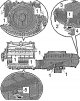
Note: When replacing parts, please take into account the applicability; simultaneous installation of parts from different manufacturers is not allowed. The following figure shows the evaporator housing manufactured by...
Note: When replacing parts, please take into account the applicability; simultaneous installation of parts from different manufacturers is not allowed. The following figure shows the evaporator housing manufactured by...
Removal and installation the evaporator
Remove the heater and air conditioning module. Remove the supply fan "V2". Remove the air intake pipe. Unscrew the screws "1" (1.5 Nm). Unlock the fastening plates "4" and "5" "arrows". Disconnect the upper part of the...
Remove the heater and air conditioning module. Remove the supply fan "V2". Remove the air intake pipe. Unscrew the screws "1" (1.5 Nm). Unlock the fastening plates "4" and "5" "arrows". Disconnect the upper part of the...

Removal and installation the drain hose, checking
Remove the right side trim of the center console. Warning! The airbag control unit may malfunction if water gets into connector "4". Fold the floor covering back so that the drain hose is visible. Disconnect the...
Remove the right side trim of the center console. Warning! The airbag control unit may malfunction if water gets into connector "4". Fold the floor covering back so that the drain hose is visible. Disconnect the...

Removal and installation of actuator motors
Removal and installation of the actuator motor of the air recirculation flap "V113" Heater and air conditioning system with manual control and electric damper drives. Note: Instead of a potentiometer, the actuator motor...
Removal and installation of the actuator motor of the air recirculation flap "V113" Heater and air conditioning system with manual control and electric damper drives. Note: Instead of a potentiometer, the actuator motor...
This section is available on russian, bulgarian, belarusian, ukrainian, serbian, croatian, romanian, polish, slovak, hungarian
Read similar sections on other Skoda models
➧ Body and interior: Interior heating Skoda Fabia 1 (1999-2007)
➧ Body and interior: Heating and air conditioning Skoda Rapid 1 (2012-2022)
➧ Body and interior: Heating and air conditioning Skoda Kodiaq 1 (2016-2024)
➧ Body and interior: Heating and air conditioning Skoda Yeti (2009-2017)
Link to this section in various formats
TEXTHTMLBB Code
- General information
- User manual
- Car driving
- Maintenance
- Petrol engines 1.2 l
- Engine repair
- Cooling system
- Supply system
- Petrol engines 1.4 l
- Engine repair
- Supply system
- Petrol engines 1.8/2.0 l
- Engine repair
- Cooling system
- Supply system
- Diesel engines 1.6/2.0 l
- Engine repair
- Cooling system
- Supply system
- Transmission
- Mechanical gearbox 02S
- Automatic gearbox 0CW
- Automatic gearbox 0D9
- Chassis (running gear)
- Front suspension
- Rear suspension
- Brake system
- Steering
- Body and interior
- Doors, locks and windows
- Exterior (external elements)
- Interior (internal elements)
- Ventilation and air conditioning
- Electrical equipment
- Equipment and devices
- Headlights and lighting
- Wiring diagrams (basic)
- Wiring diagrams (comfort)
- General information
- Vehicle details
- Maintenance
- Power unit
- Petrol engines 1.6 l AEE
- Petrol engines 1.8 l AGN
- Diesel engines 1.9 l AGR
- Fuel system
- Exhaust system
- Cooling system
- Transmission
- Clutch
- Car gearbox
- Gearbox repair 02J
- Gearbox repair 02K
- Chassis (running gear)
- Wheels and tires
- Suspension and axles
- Brake system
- Body and interior
- Exterior (external elements)
- Interior (internal elements)
- Doors, locks and windows
- Electrical equipment
- Equipment and devices
- Electrical circuits