



Brake system of the car Skoda Octavia 3

Parts and components — ABS/ESC
1. ABS/ESC control unit "N04": Installation location: on left-hand drive vehicles - in the engine compartment on the right. Installation location: on right-hand drive vehicles - in the engine compartment on the left;...
1. ABS/ESC control unit "N04": Installation location: on left-hand drive vehicles - in the engine compartment on the right. Installation location: on right-hand drive vehicles - in the engine compartment on the left;...

Parts and components of the hydraulic unit, brake booster
1. ABS/ESC control unit "J104" 2. Hydraulic unit ABS "N55" 3. Screw 4. Brake pipe, 14 Nm: to the rear right brake caliper. Identification: diameter 5.25 mm and hollow screw with long thread M12 x 1 5. Brake pipe, 14 Nm:...
1. ABS/ESC control unit "J104" 2. Hydraulic unit ABS "N55" 3. Screw 4. Brake pipe, 14 Nm: to the rear right brake caliper. Identification: diameter 5.25 mm and hollow screw with long thread M12 x 1 5. Brake pipe, 14 Nm:...

Removal and installation of the ECU and hydraulic unit
Cars with gasoline engines Installation location: The ECU is connected to the hydraulic unit using threaded connections and is located in the engine compartment on the right side. Caution! Do not bend the brake lines at...
Cars with gasoline engines Installation location: The ECU is connected to the hydraulic unit using threaded connections and is located in the engine compartment on the right side. Caution! Do not bend the brake lines at...

Removal and installation the hydraulic unit bracket
Remove the hydraulic unit. Unscrew nuts "4". Remove bracket "3" from the car. Installation Installation in reverse order. Tightening torques
Remove the hydraulic unit. Unscrew nuts "4". Remove bracket "3" from the car. Installation Installation in reverse order. Tightening torques

Parts and assemblies of ABS speed sensors on the front axle
1. ABS speed sensor: before replacing the sensor, clean the inner surface of the hole and lubricate with heat-resistant thread paste "G 052112 AZ" 2. Bolt, 8 Nm 3. Wheel hub with wheel hub bearing: The ABS sensor...
1. ABS speed sensor: before replacing the sensor, clean the inner surface of the hole and lubricate with heat-resistant thread paste "G 052112 AZ" 2. Bolt, 8 Nm 3. Wheel hub with wheel hub bearing: The ABS sensor...

Removal and installation the ABS speed sensor on the front axle
Raise the vehicle. Disconnect the speed sensor connector "1"/speed sensor wire. Remove screw "2" from the wheel hub bearing housing. Remove the ABS speed sensor from the wheel hub bearing housing. Installation Before...
Raise the vehicle. Disconnect the speed sensor connector "1"/speed sensor wire. Remove screw "2" from the wheel hub bearing housing. Remove the ABS speed sensor from the wheel hub bearing housing. Installation Before...

ABS speed sensor components and assemblies on the rear axle
1. ABS speed sensor: before replacing the sensor, clean the inner surface of the hole and lubricate with heat-resistant thread paste "G 052 112 AZ" 2. Bolt, 8 Nm 3. Wheel hub with wheel hub bearing: The ABS sensor...
1. ABS speed sensor: before replacing the sensor, clean the inner surface of the hole and lubricate with heat-resistant thread paste "G 052 112 AZ" 2. Bolt, 8 Nm 3. Wheel hub with wheel hub bearing: The ABS sensor...

Removal and installation the ABS speed sensor on the rear axle
Note: Removal and installation of ABS speed sensors for trailing arm suspension is performed in the same way as for multi-link suspension. Raise the vehicle. Disconnect the speed sensor connector "1"/speed sensor wire....
Note: Removal and installation of ABS speed sensors for trailing arm suspension is performed in the same way as for multi-link suspension. Raise the vehicle. Disconnect the speed sensor connector "1"/speed sensor wire....

Replacing Front Brake Pads — Installation Instructions
When replacing brake pads, consider the following: check the protective cover of the brake caliper piston. If damaged, replace the protective cover. When replacing the cuff: check the working surfaces of the brake...
When replacing brake pads, consider the following: check the protective cover of the brake caliper piston. If damaged, replace the protective cover. When replacing the cuff: check the working surfaces of the brake...

Front brake repair, brake caliper PC 57
Note: Follow the instructions for replacing the brake pads. After replacing the brake pads, press the brake pedal firmly several times with the vehicle stationary until the brake pads are in their operating position....
Note: Follow the instructions for replacing the brake pads. After replacing the brake pads, press the brake pedal firmly several times with the vehicle stationary until the brake pads are in their operating position....

Removal and installation of brake pads of the brake mechanism PC 57
Mark the brake pads to be used again when removing them. They should be installed in their original places, otherwise uneven braking will occur! Remove the wheels. Disconnect connector "1" of the brake pad wear...
Mark the brake pads to be used again when removing them. They should be installed in their original places, otherwise uneven braking will occur! Remove the wheels. Disconnect connector "1" of the brake pad wear...

Removal and installation the brake caliper PC 57
Follow the instructions for replacing the brake pads. Note: The procedure is only valid for replacing or subsequently repairing the brake caliper. Remove the wheels. Disconnect the connector of the brake pad wear...
Follow the instructions for replacing the brake pads. Note: The procedure is only valid for replacing or subsequently repairing the brake caliper. Remove the wheels. Disconnect the connector of the brake pad wear...

Front brake repair, brake caliper C60
Note: Follow the instructions for replacing the brake pads. After replacing the brake pads, press the brake pedal firmly several times with the vehicle stationary until the brake pads are in their operating position....
Note: Follow the instructions for replacing the brake pads. After replacing the brake pads, press the brake pedal firmly several times with the vehicle stationary until the brake pads are in their operating position....

Removal and installation brake pads (brakes C60)
Mark the brake pads to be used again when removing them. They should be installed in their original places, otherwise uneven braking will occur! Remove the wheels. Disconnect connector "1" of the brake pad wear...
Mark the brake pads to be used again when removing them. They should be installed in their original places, otherwise uneven braking will occur! Remove the wheels. Disconnect connector "1" of the brake pad wear...

Removal and installation of brake caliper C60
Follow the instructions for replacing the brake pads. Note: The procedure is only valid for replacing or subsequently repairing the brake caliper. Remove the wheels. Disconnect the connector of the brake pad wear...
Follow the instructions for replacing the brake pads. Note: The procedure is only valid for replacing or subsequently repairing the brake caliper. Remove the wheels. Disconnect the connector of the brake pad wear...

Front brake repair, disc brake mechanism with floating caliper FS-III
Note: Follow the instructions for replacing the brake pads. After replacing the brake pads, press the brake pedal firmly several times with the vehicle stationary until the brake pads are in their operating position....
Note: Follow the instructions for replacing the brake pads. After replacing the brake pads, press the brake pedal firmly several times with the vehicle stationary until the brake pads are in their operating position....

Removal and installation brake pads, disc brake mechanism with floating caliper FS-III
Mark the brake pads to be used again when removing them. They should be installed in their original places, otherwise uneven braking will occur! Remove the wheels. Remove the protective caps "see arrows". Unscrew both...
Mark the brake pads to be used again when removing them. They should be installed in their original places, otherwise uneven braking will occur! Remove the wheels. Remove the protective caps "see arrows". Unscrew both...

Removal and installation the brake caliper, disc brake mechanism with floating caliper FS-III
The following procedure is only valid for replacing or subsequently repairing the brake caliper. Remove the wheels. Attach the air bleed hose to the brake caliper bleed nipple and then open the bleed nipple. Install a...
The following procedure is only valid for replacing or subsequently repairing the brake caliper. Remove the wheels. Attach the air bleed hose to the brake caliper bleed nipple and then open the bleed nipple. Install a...
Rear Brake Repair — General Information
Replacing the rear wheel brake pads - installation instructions When replacing brake pads, consider the following: check the protective cover of the brake caliper piston. If damaged, replace the protective cover. When...
Replacing the rear wheel brake pads - installation instructions When replacing brake pads, consider the following: check the protective cover of the brake caliper piston. If damaged, replace the protective cover. When...

Repair of rear brakes C38
Note: Observe the installation instructions. After replacing the brake pads, press the brake pedal firmly several times with the vehicle stationary until the brake pads are in their operating position. Use a brake fluid...
Note: Observe the installation instructions. After replacing the brake pads, press the brake pedal firmly several times with the vehicle stationary until the brake pads are in their operating position. Use a brake fluid...

Removal and installation brake pads (C 38)
Mark the brake pads to be used again when removing them. They should be installed in their original places, otherwise uneven braking will occur! Remove the wheels. Unscrew the brake shield mounting screws, while holding...
Mark the brake pads to be used again when removing them. They should be installed in their original places, otherwise uneven braking will occur! Remove the wheels. Unscrew the brake shield mounting screws, while holding...

Removal and installation the brake caliper (C 38)
The following procedure is only valid for replacing or subsequently repairing the brake caliper. Remove the wheels. Press the lever "2" in the "direction of the arrow" and disconnect the parking brake cable "3". Release...
The following procedure is only valid for replacing or subsequently repairing the brake caliper. Remove the wheels. Press the lever "2" in the "direction of the arrow" and disconnect the parking brake cable "3". Release...

Rear brake repair (PC 38 HRA)
Follow the installation instructions. After replacing the brake pads, press the brake pedal firmly several times with the vehicle stationary until the brake pads are in their operating position. Use a brake fluid...
Follow the installation instructions. After replacing the brake pads, press the brake pedal firmly several times with the vehicle stationary until the brake pads are in their operating position. Use a brake fluid...

Removal and installation brake pads (PC38HRA)
Mark the brake pads to be used again when removing them. They should be installed in their original places, otherwise uneven braking will occur! Remove the wheels. Unscrew the brake shield mounting screws, while holding...
Mark the brake pads to be used again when removing them. They should be installed in their original places, otherwise uneven braking will occur! Remove the wheels. Unscrew the brake shield mounting screws, while holding...

Removal and installation the brake caliper (PC 38 HRA)
The following procedure is only valid for replacing or subsequently repairing the brake caliper. Remove the wheels. Press the lever "2" in the "direction of the arrow" and disconnect the parking brake cable "3". Release...
The following procedure is only valid for replacing or subsequently repairing the brake caliper. Remove the wheels. Press the lever "2" in the "direction of the arrow" and disconnect the parking brake cable "3". Release...

Parking brake lever — general installation diagram
1. Handbrake lever: Remove the center console before removing 2. Bolt, 20 Nm + 90°: replace after each removal 3. Traction 4. Leveling bracket 5. Adjusting nut 6. Handbrake cable 7. Parking brake control switch 8....
1. Handbrake lever: Remove the center console before removing 2. Bolt, 20 Nm + 90°: replace after each removal 3. Traction 4. Leveling bracket 5. Adjusting nut 6. Handbrake cable 7. Parking brake control switch 8....

Adjusting the parking brake
Primary adjustment is only required when replacing the parking brake cable, brake caliper or after replacing the brake discs. Remove the armrest. Press the brake pedal firmly (min. 3 times). Apply and release the...
Primary adjustment is only required when replacing the parking brake cable, brake caliper or after replacing the brake discs. Remove the armrest. Press the brake pedal firmly (min. 3 times). Apply and release the...

Removal and installation the handbrake cable
Release the handbrake. Remove the armrest. Loosen the adjusting nut "1" so that the corresponding parking brake cable "2" can be released from the alignment bracket "3". Release the spring bushing "1" of the parking...
Release the handbrake. Remove the armrest. Loosen the adjusting nut "1" so that the corresponding parking brake cable "2" can be released from the alignment bracket "3". Release the spring bushing "1" of the parking...

Removal and installation the handbrake cable lever trim
Release the handbrake. Remove the parking brake lever trim with wedge "3409" "A". Disconnect the parking brake lever trim. Mark the point on the release button as shown in the picture. Carefully drill a 4mm deep hole at...
Release the handbrake. Remove the parking brake lever trim with wedge "3409" "A". Disconnect the parking brake lever trim. Mark the point on the release button as shown in the picture. Carefully drill a 4mm deep hole at...

Brake pedal — design description
Caution! The brake pedal travel must not be reduced by additional floor coverings. Before installation, lubricate all bearings with polyurea grease "G 052142 A2". The brake light switch "F" and the brake pedal switch...
Caution! The brake pedal travel must not be reduced by additional floor coverings. Before installation, lubricate all bearings with polyurea grease "G 052142 A2". The brake light switch "F" and the brake pedal switch...
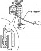
Disconnecting the brake pedal from the brake booster and connecting it to the brake booster
Remove the driver's side trim. First, press the brake pedal towards the brake booster and hold it. 2. Pusher 3. Retaining tabs Install the release tool -T10159A- and pull it towards the driver's seat, while holding the...
Remove the driver's side trim. First, press the brake pedal towards the brake booster and hold it. 2. Pusher 3. Retaining tabs Install the release tool -T10159A- and pull it towards the driver's seat, while holding the...

Removal and installation the brake pedal
It is impossible to remove the brake pedal in the car. Remove the support bracket. Unscrew the support pin "in the direction of the arrow". Break off the clamps "B". Remove the support pin. Remove the brake pedal....
It is impossible to remove the brake pedal in the car. Remove the support bracket. Unscrew the support pin "in the direction of the arrow". Break off the clamps "B". Remove the support pin. Remove the brake pedal....

Removal and installation the support bracket
Disconnect the battery. Remove the knee airbag. Remove the left footwell nozzle. Remove the gateway control unit. Remove the safety frame crossmember "1". Disconnect connector "2" of the adaptive lighting and headlight...
Disconnect the battery. Remove the knee airbag. Remove the left footwell nozzle. Remove the gateway control unit. Remove the safety frame crossmember "1". Disconnect connector "2" of the adaptive lighting and headlight...

Removal and installation the brake light switch
Remove the suction pipe connecting hose. Disconnect connector "1" from brake light switch "F" "2". Unscrew the mounting screw from brake light switch "F" "2". Remove brake light switch "F" "2". Installation Installation...
Remove the suction pipe connecting hose. Disconnect connector "1" from brake light switch "F" "2". Unscrew the mounting screw from brake light switch "F" "2". Remove brake light switch "F" "2". Installation Installation...

Repair of the front brake caliper
Repair of brake caliper C 57 Note: When performing repairs, install the entire repair kit. Use only alcohol to clean the brake system. Lubricate the brake cylinder, piston and sealing ring with a thin layer of lithium...
Repair of brake caliper C 57 Note: When performing repairs, install the entire repair kit. Use only alcohol to clean the brake system. Lubricate the brake cylinder, piston and sealing ring with a thin layer of lithium...

Repair of the rear brake caliper
When performing repairs, install the entire repair kit. Use only alcohol to clean the brake caliper. Lubricate the brake cylinder, piston and sealing ring with a thin layer of lithium grease "G 052150 A2". In case of...
When performing repairs, install the entire repair kit. Use only alcohol to clean the brake caliper. Lubricate the brake cylinder, piston and sealing ring with a thin layer of lithium grease "G 052150 A2". In case of...

Repair of brake caliper PC 38 HRA
Note: When performing repairs, install the entire repair kit. Use only alcohol to clean the brake caliper. Lubricate the brake cylinder, piston and sealing ring with a thin layer of lithium grease "G 052 150 A2". In...
Note: When performing repairs, install the entire repair kit. Use only alcohol to clean the brake caliper. Lubricate the brake cylinder, piston and sealing ring with a thin layer of lithium grease "G 052 150 A2". In...

Brake booster/master cylinder
1. Nuts, 25 Nm 2. Pedal mechanism 3. Front wall 4. Nut, self-locking, 23 Nm: replace after each removal 5. Master brake cylinder: cannot be repaired; if faulty, replace completely 6. Brake light switch "F": Installation...
1. Nuts, 25 Nm 2. Pedal mechanism 3. Front wall 4. Nut, self-locking, 23 Nm: replace after each removal 5. Master brake cylinder: cannot be repaired; if faulty, replace completely 6. Brake light switch "F": Installation...

Removal and installation the master brake cylinder
Remove the battery. Remove the air filter. Remove the battery bracket. For cars with a radio with coding, check for the code, request it if necessary. Remove the suction pipe connecting hose. Place a sufficient amount...
Remove the battery. Remove the air filter. Remove the battery bracket. For cars with a radio with coding, check for the code, request it if necessary. Remove the suction pipe connecting hose. Place a sufficient amount...

Removal and installation the brake booster
Reduce the vacuum in the brake booster by pressing the brake pedal several times. Remove the brake master cylinder. Disconnect the vacuum hose from the brake booster. Disconnect the brake pedal from the brake booster....
Reduce the vacuum in the brake booster by pressing the brake pedal several times. Remove the brake master cylinder. Disconnect the vacuum hose from the brake booster. Disconnect the brake pedal from the brake booster....

Vacuum System — Checking the Check Valve
The check valve must let air through in the direction of arrow "A". In the opposite direction, the check valve must be closed. Pay attention to the correct installation position!
The check valve must let air through in the direction of arrow "A". In the opposite direction, the check valve must be closed. Pay attention to the correct installation position!

Removal and installation the vacuum sensor «G 608»
The vacuum sensor "G 608" is installed depending on the vehicle configuration. Disconnect connector "1" of the vacuum sensor "G 608" "2". Disconnect the vacuum hose from the brake booster. Remove the vacuum sensor "G...
The vacuum sensor "G 608" is installed depending on the vehicle configuration. Disconnect connector "1" of the vacuum sensor "G 608" "2". Disconnect the vacuum hose from the brake booster. Remove the vacuum sensor "G...

Vacuum system — cars with gasoline engines
1. Screw 2. High pressure pump 3. Replace the O-ring after each removal 4. Bolt, 9 Nm 5. Seal: Replace after each removal 6. Cooling system pipe 7. Vacuum hose 8. Vacuum pump 9. Bolt, 9 Nm. Remove the high pressure...
1. Screw 2. High pressure pump 3. Replace the O-ring after each removal 4. Bolt, 9 Nm 5. Seal: Replace after each removal 6. Cooling system pipe 7. Vacuum hose 8. Vacuum pump 9. Bolt, 9 Nm. Remove the high pressure...
This section is available on russian, bulgarian, belarusian, ukrainian, serbian, croatian, romanian, polish, slovak, hungarian
Read similar sections on other Skoda models
➧ Chassis (running gear): Brake system Skoda Fabia 1 (1999-2007)
➧ Chassis (running gear): Brake system Skoda Rapid 1 (2012-2022)
➧ Chassis (running gear): Brake system Skoda Superb 2 (2008-2015)
➧ Chassis (running gear): Brake system Skoda Kodiaq 1 (2016-2024)
➧ Chassis (running gear): Brake system Skoda Yeti (2009-2017)
➧ Chassis (running gear): Brake system Skoda Felicia (1994-2001)
Link to this section in various formats
TEXTHTMLBB Code
- General information
- User manual
- Car driving
- Maintenance
- Petrol engines 1.2 l
- Engine repair
- Cooling system
- Supply system
- Petrol engines 1.4 l
- Engine repair
- Supply system
- Petrol engines 1.8/2.0 l
- Engine repair
- Cooling system
- Supply system
- Diesel engines 1.6/2.0 l
- Engine repair
- Cooling system
- Supply system
- Transmission
- Mechanical gearbox 02S
- Automatic gearbox 0CW
- Automatic gearbox 0D9
- Chassis (running gear)
- Front suspension
- Rear suspension
- Brake system
- Steering
- Body and interior
- Doors, locks and windows
- Exterior (external elements)
- Interior (internal elements)
- Ventilation and air conditioning
- Electrical equipment
- Equipment and devices
- Headlights and lighting
- Wiring diagrams (basic)
- Wiring diagrams (comfort)
- General information
- Vehicle details
- Maintenance
- Power unit
- Petrol engines 1.6 l AEE
- Petrol engines 1.8 l AGN
- Diesel engines 1.9 l AGR
- Fuel system
- Exhaust system
- Cooling system
- Transmission
- Clutch
- Car gearbox
- Gearbox repair 02J
- Gearbox repair 02K
- Chassis (running gear)
- Wheels and tires
- Suspension and axles
- Brake system
- Body and interior
- Exterior (external elements)
- Interior (internal elements)
- Doors, locks and windows
- Electrical equipment
- Equipment and devices
- Electrical circuits