



Electrical equipment and appliances Skoda Octavia 3

Disconnecting the battery
Switch off all electrical consumers, switch off the ignition and remove the ignition key from the lock. Open the cover of the heat-protective cover. Open the cover "1", loosen the nut "3" and only then disconnect the...
Switch off all electrical consumers, switch off the ignition and remove the ignition key from the lock. Open the cover of the heat-protective cover. Open the cover "1", loosen the nut "3" and only then disconnect the...

Procedure for performing work when connecting the battery
Caution! After working on the airbag system or on the electric seat belt tensioners or seat belts, the following instructions must also be followed. Before connecting the battery, switch on the ignition. No one must be...
Caution! After working on the airbag system or on the electric seat belt tensioners or seat belts, the following instructions must also be followed. Before connecting the battery, switch on the ignition. No one must be...

Removal and installation the battery
Switch off all electrical consumers, switch off the ignition and remove the ignition key from the lock. Open the cover of the heat-protective cover. Open cover "4", loosen nut "6" and disconnect the ground cable of...
Switch off all electrical consumers, switch off the ignition and remove the ignition key from the lock. Open the cover of the heat-protective cover. Open cover "4", loosen nut "6" and disconnect the ground cable of...

Removal and installation the battery bracket
Remove the air filter housing located in front of the battery (not applicable to 1.2 L engines, TSI; 1.4 l, TSI). Remove the battery. Unscrew the "arrow" screws (9 Nm) and remove the battery bracket "1". Installation in...
Remove the air filter housing located in front of the battery (not applicable to 1.2 L engines, TSI; 1.4 l, TSI). Remove the battery. Unscrew the "arrow" screws (9 Nm) and remove the battery bracket "1". Installation in...

Removal and installation the starter
Disconnect the battery cable to ground. Remove the air filter housing located in front of the battery (not applicable to 1.2 L engines, TSI; 1.4 l, TSI). Move the protective cover "see arrow". Unscrew nut "3" and...
Disconnect the battery cable to ground. Remove the air filter housing located in front of the battery (not applicable to 1.2 L engines, TSI; 1.4 l, TSI). Move the protective cover "see arrow". Unscrew nut "3" and...

Removal and installation the generator
Disconnect the battery ground wire. Remove the poly V-belt. Cars with TDI engine Remove the fuel filter and set aside 8 side (the hoses cannot be disconnected). Cars with TDI engine and TSI engines with a capacity of...
Disconnect the battery ground wire. Remove the poly V-belt. Cars with TDI engine Remove the fuel filter and set aside 8 side (the hoses cannot be disconnected). Cars with TDI engine and TSI engines with a capacity of...

Removal and installation voltage regulators
Removal and installation a Bosch voltage regulator Carefully pry off and remove cover "1" from the generator, the protective cover. Unscrew the fastening screws "see arrows" (2 Nm) of the voltage regulator and remove...
Removal and installation a Bosch voltage regulator Carefully pry off and remove cover "1" from the generator, the protective cover. Unscrew the fastening screws "see arrows" (2 Nm) of the voltage regulator and remove...

Removal and installation the poly V-belt pulley
Removal and installation a poly V-belt pulley on a three-phase alternator Remove the poly V-belt and, accordingly, the generator. Remove the poly V-belt pulley using the "T30032" attachment. Removal - turn the generator...
Removal and installation a poly V-belt pulley on a three-phase alternator Remove the poly V-belt and, accordingly, the generator. Remove the poly V-belt pulley using the "T30032" attachment. Removal - turn the generator...

Adaptive cruise control, Front Assist
1. Instrument cluster: with instrument cluster control unit "J285" 2. Steering column switch cluster: optional with adaptive cruise control 3. Adaptive cruise control switch "E45": only for vehicles with adaptive cruise...
1. Instrument cluster: with instrument cluster control unit "J285" 2. Steering column switch cluster: optional with adaptive cruise control 3. Adaptive cruise control switch "E45": only for vehicles with adaptive cruise...

Removal and installation the adaptive cruise control unit «J428»
Note: If the adaptive cruise control control unit "J428" is replaced, connect the Tester and in the "Guided fault finding" or "Guided functions" mode select the "Replace the corresponding control unit" function. Switch...
Note: If the adaptive cruise control control unit "J428" is replaced, connect the Tester and in the "Guided fault finding" or "Guided functions" mode select the "Replace the corresponding control unit" function. Switch...

Instrument cluster
Instrument cluster equipment The instrument cluster is available in three versions: 1) Basic configuration with segment display "Basic": without multifunctional display, with multifunctional display; 2) Instrument...
Instrument cluster equipment The instrument cluster is available in three versions: 1) Basic configuration with segment display "Basic": without multifunctional display, with multifunctional display; 2) Instrument...

Control lamps in the instrument panel insert
Note: The location and number of indicator lamps depends on the vehicle equipment and the type of instrument cluster. 1. Fastening the front seat belts 2. Tire pressure 3. Power steering 4. Engine electronics control...
Note: The location and number of indicator lamps depends on the vehicle equipment and the type of instrument cluster. 1. Fastening the front seat belts 2. Tire pressure 3. Power steering 4. Engine electronics control...
Multimedia Infotainment System — General Information
Infotainment system = Multimedia information system (MIB - Modular Infotainment System). It allows the driver to access the car settings, auxiliary systems and comfort functions via certain applications. Even in its...
Infotainment system = Multimedia information system (MIB - Modular Infotainment System). It allows the driver to access the car settings, auxiliary systems and comfort functions via certain applications. Even in its...

Infotainment system configurations
Basic infotainment system (entry) - Blues, Swing versions Blues: Monochromatic display, media inputs - Aux-In connectors; USB/MEDIA IN (Mitsumi), AM/FM radio, display and adjustment of car comfort functions. Additional...
Basic infotainment system (entry) - Blues, Swing versions Blues: Monochromatic display, media inputs - Aux-In connectors; USB/MEDIA IN (Mitsumi), AM/FM radio, display and adjustment of car comfort functions. Additional...

Parts and components of the infotainment system
Infotainment system parts and components - complete with radio receiver The number and design of components depend on the vehicle configuration. 1. Front tweeter 2. Multifunctional steering wheel 3. Rear tweeter 4....
Infotainment system parts and components - complete with radio receiver The number and design of components depend on the vehicle configuration. 1. Front tweeter 2. Multifunctional steering wheel 3. Rear tweeter 4....
Electronic coding for protection against theft
The display module/control unit has an electronic anti-theft protection system that operates in conjunction with the instrument cluster. The display module/control unit must be adapted to the respective vehicle using...
The display module/control unit has an electronic anti-theft protection system that operates in conjunction with the instrument cluster. The display module/control unit must be adapted to the respective vehicle using...

Display module/control unit for infotainment system
Display module/control unit for infotainment system "Blues" and "Swing" The display module/infotainment control unit form a single unit. Remove any media left in the device. Switch off the ignition and all electrical...
Display module/control unit for infotainment system "Blues" and "Swing" The display module/infotainment control unit form a single unit. Remove any media left in the device. Switch off the ignition and all electrical...

Antenna Systems Review
Note: The number of components of the antenna system depends on the vehicle equipment. When the vehicle is equipped with the "Blues" and "Swing" infotainment systems, the display module "pos. 3" and the control unit...
Note: The number of components of the antenna system depends on the vehicle equipment. When the vehicle is equipped with the "Blues" and "Swing" infotainment systems, the display module "pos. 3" and the control unit...

Removal and installation the roof antenna
Disconnect the upper trim of the B pillar and remove the upper trim of the C and D pillars (Combi). Loosen the ceiling trim fastening and carefully hang its rear part down. Unlock and disconnect the connectors "1" of...
Disconnect the upper trim of the B pillar and remove the upper trim of the C and D pillars (Combi). Loosen the ceiling trim fastening and carefully hang its rear part down. Unlock and disconnect the connectors "1" of...

Removal and installation a frequency filter
Removal and installation a frequency filter for frequency modulation (FM) in the positive wire "R179" Remove the inner trim of the luggage compartment door. Disconnect connectors "1" and "3". Unscrew the screw "arrow...
Removal and installation a frequency filter for frequency modulation (FM) in the positive wire "R179" Remove the inner trim of the luggage compartment door. Disconnect connectors "1" and "3". Unscrew the screw "arrow...

Removal and installation the antenna module (amplifier) AM/FM and FM2/DAB
Note: The procedure for removal and installation is the same for both amplifiers. Octavia Remove the inner trim of the luggage compartment door. Combi Remove the upper trim of the C-pillar on the side where the antenna...
Note: The procedure for removal and installation is the same for both amplifiers. Octavia Remove the inner trim of the luggage compartment door. Combi Remove the upper trim of the C-pillar on the side where the antenna...

Mobile Phone Connection Kit — Design Description
Note: The number of components in the kit depends on the vehicle configuration. 1. Microphone for phone "R38": in the front interior light 2. Infotainment control unit: with built-in Bluetooth module 3. Infotainment...
Note: The number of components in the kit depends on the vehicle configuration. 1. Microphone for phone "R38": in the front interior light 2. Infotainment control unit: with built-in Bluetooth module 3. Infotainment...

Removal and installation an amplifier for receiving an antenna signal (compensator)
The compensator is located on the right under the luggage compartment trim. Remove the right side luggage compartment trim. Unscrew the screws "arrows" (5 Nm). Octavia Combi Disconnect the connector and remove amplifier...
The compensator is located on the right under the luggage compartment trim. Remove the right side luggage compartment trim. Unscrew the screws "arrows" (5 Nm). Octavia Combi Disconnect the connector and remove amplifier...

Removal and installation the induction board
Remove the small item storage compartment in the front of the center console. Release the induction board "2" from the "arrow" clips and remove it from the storage compartment "1". Installation in reverse order....
Remove the small item storage compartment in the front of the center console. Release the induction board "2" from the "arrow" clips and remove it from the storage compartment "1". Installation in reverse order....

Microphone of the phone «R38»
Remove the front interior light fixture. Release the microphone from the retaining tabs "see arrows". Disconnect the connector. Installation in reverse order.
Remove the front interior light fixture. Release the microphone from the retaining tabs "see arrows". Disconnect the connector. Installation in reverse order.

Multifunctional steering wheel
Note: In case of complaint, it is necessary to know the functions and operation of the multifunction steering wheel. The multifunctional steering wheel includes (depending on the configuration) the following units:...
Note: In case of complaint, it is necessary to know the functions and operation of the multifunction steering wheel. The multifunctional steering wheel includes (depending on the configuration) the following units:...

Canton Acoustic System — Design Description
1. Front tweeter 2. Center speaker: in the middle of the front panel 3. Rear tweeter 4. Subwoofer 5. Rear midrange speaker 6. Acoustic system control unit 7. Front midrange speaker
1. Front tweeter 2. Center speaker: in the middle of the front panel 3. Rear tweeter 4. Subwoofer 5. Rear midrange speaker 6. Acoustic system control unit 7. Front midrange speaker

Removal and installation of acoustic system elements
Removal and installation the acoustic system control unit Switch off all electrical consumers and remove the ignition key. Set the left front seat as far back as it will go and to the highest position. Remove the spacer...
Removal and installation the acoustic system control unit Switch off all electrical consumers and remove the ignition key. Set the left front seat as far back as it will go and to the highest position. Remove the spacer...
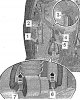
Removal and installation the windshield washer pump and reservoir
The operation of the windshield washer can be checked using the Tester through diagnostics of the executive body of the on-board network control unit "3519". Note: Depending on the configuration, the position of...
The operation of the windshield washer can be checked using the Tester through diagnostics of the executive body of the on-board network control unit "3519". Note: Depending on the configuration, the position of...

Removal and installation windshield washer nozzles
Removal and installation windshield washer nozzles Remove the windshield wiper arms. Remove the water drain box cover. Carefully pry the elbows off the nozzles from below and disconnect the connectors (at heated...
Removal and installation windshield washer nozzles Remove the windshield wiper arms. Remove the water drain box cover. Carefully pry the elbows off the nozzles from below and disconnect the connectors (at heated...

Headlight washer
Removal and installation headlight washer nozzle lifting cylinders Remove the front bumper. Push the injectors with the cover out of the bumper (from the inside) so that you can grab the cover. Pull the cover out a...
Removal and installation headlight washer nozzle lifting cylinders Remove the front bumper. Push the injectors with the cover out of the bumper (from the inside) so that you can grab the cover. Pull the cover out a...

Windshield cleaner
Removal and installation windshield wiper arms with brushes and adjusting their end position Note: If the windscreen wiper motor needs to be switched on during work, the bonnet must be closed and the ignition must be...
Removal and installation windshield wiper arms with brushes and adjusting their end position Note: If the windscreen wiper motor needs to be switched on during work, the bonnet must be closed and the ignition must be...

Rear window wiper
Removal and installation the windshield wiper arm with the brush and adjusting their end position Unlock and remove cap "1". Carefully remove nozzle "2" "arrow" (not for Combi). Loosen the fastening nut one turn. Place...
Removal and installation the windshield wiper arm with the brush and adjusting their end position Unlock and remove cap "1". Carefully remove nozzle "2" "arrow" (not for Combi). Loosen the fastening nut one turn. Place...

Steering column switch module — design description
Self-diagnosis and fault indication The steering column control unit "J527" is equipped with self-diagnosis, which facilitates troubleshooting. To troubleshoot, use the "Guided troubleshooting" function in the Tester....
Self-diagnosis and fault indication The steering column control unit "J527" is equipped with self-diagnosis, which facilitates troubleshooting. To troubleshoot, use the "Guided troubleshooting" function in the Tester....

Removal and installation the steering column switch module
Remove the steering wheel. Before removing the steering wheel from the steering column, set the wheels to the straight-ahead position. Remove the upper and lower steering column trims. Remove the connector stopper "4",...
Remove the steering wheel. Before removing the steering wheel from the steering column, set the wheels to the straight-ahead position. Remove the upper and lower steering column trims. Remove the connector stopper "4",...
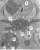
Removal and installation the steering column control unit «J527»
Note: The airbag coil spring and the return ring with the slip ring "F138" are integrated into the steering column control unit "J527". If the control unit is replaced, the "Replace control unit" function of the...
Note: The airbag coil spring and the return ring with the slip ring "F138" are integrated into the steering column control unit "J527". If the control unit is replaced, the "Replace control unit" function of the...

Removal and installation the steering column lock housing
Remove the steering wheel, lower and upper steering column trim. Remove the steering column switch module. Disconnect connectors "1" and "3". Drill out the "arrow" screws using an angle drill and an 8.5 mm drill bit....
Remove the steering wheel, lower and upper steering column trim. Remove the steering column switch module. Disconnect connectors "1" and "3". Drill out the "arrow" screws using an angle drill and an 8.5 mm drill bit....

Removal and installation the electronic steering column lock control unit «J764»
Note: If the control unit is replaced, the "Replace control unit" function of the corresponding control unit must be selected. Remove the steering wheel, lower and upper steering column trim. Remove the steering column...
Note: If the control unit is replaced, the "Replace control unit" function of the corresponding control unit must be selected. Remove the steering wheel, lower and upper steering column trim. Remove the steering column...
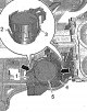
Removal and installation the ignition and starter switch
Note: Do not remove the steering wheel. To remove the screws securing the lower steering column trim, turn the steering wheel 90° to the left and then to the right. Remove the upper and lower steering column trims....
Note: Do not remove the steering wheel. To remove the screws securing the lower steering column trim, turn the steering wheel 90° to the left and then to the right. Remove the upper and lower steering column trims....

Unlocking car doors/steering lock without a key, Start/Stop without a key — KESSY system
General description KESSY System (Keyless Entry, Start and exit SYstem - keyless entry and engine start authorization system) allows you to unlock and lock the car, as well as start and stop the engine without a key. It...
General description KESSY System (Keyless Entry, Start and exit SYstem - keyless entry and engine start authorization system) allows you to unlock and lock the car, as well as start and stop the engine without a key. It...

KESSY system antennas
Removal and installation the antenna under the center console The antenna is located in the bracket in front of the gearshift lever. Turn off the ignition and all electrical consumers. Remove the center console. Using a...
Removal and installation the antenna under the center console The antenna is located in the bracket in front of the gearshift lever. Turn off the ignition and all electrical consumers. Remove the center console. Using a...

Removal and installation the START/STOP button and the immobilizer reading coil for emergency engine start
Note: Do not remove the steering wheel. To remove the screws securing the lower steering column trim, turn the steering wheel 90° to the left and then to the right. First remove the upper and then the lower steering...
Note: Do not remove the steering wheel. To remove the screws securing the lower steering column trim, turn the steering wheel 90° to the left and then to the right. First remove the upper and then the lower steering...

Parking assistance and parking assistant — design description
Note: In case of complaint, it is essential to know the functions of the parking assistance system. The location of the contacts on the control unit and the connection of the parking assistance system components can be...
Note: In case of complaint, it is essential to know the functions of the parking assistance system. The location of the contacts on the control unit and the connection of the parking assistance system components can be...

Removal and installation parking aids
Removal and installation the parking assistance control unit "J446" or the parking assistance and parking assistant control unit "J791" Turn off the ignition and all electrical consumers. If present, remove the...
Removal and installation the parking assistance control unit "J446" or the parking assistance and parking assistant control unit "J791" Turn off the ignition and all electrical consumers. If present, remove the...

Removal and installation power window switches
Driver side switch Note: The installation procedure is identical for all types of electric window switches. When using a lever tool, seal the areas where the lever tool is inserted with regular adhesive tape. Turn off...
Driver side switch Note: The installation procedure is identical for all types of electric window switches. When using a lever tool, seal the areas where the lever tool is inserted with regular adhesive tape. Turn off...

Removal and installation the mirror adjustment switch
Remove the upper cover of the handle "1" "arrow". Disconnect switch "2" "arrows" and remove from cover "1". Disconnect the connector. Installation Installation in reverse order. Note: When pressing the switch, hold the...
Remove the upper cover of the handle "1" "arrow". Disconnect switch "2" "arrows" and remove from cover "1". Disconnect the connector. Installation Installation in reverse order. Note: When pressing the switch, hold the...

Removal and installation the glove compartment light switch on the front passenger side
Remove the storage compartment on the instrument panel on the front passenger side. Unlock switch "2" from the "arrow" latches and remove. Disconnect connector "1". Installation Installation in reverse order. Press the...
Remove the storage compartment on the instrument panel on the front passenger side. Unlock switch "2" from the "arrow" latches and remove. Disconnect connector "1". Installation Installation in reverse order. Press the...

Removal and installation of the interior security system deactivation switch «E 267» and the vehicle tilt sensor deactivation key «E 360»
Switch off the ignition and all electrical consumers. Disconnect the upper part of the lower trim of the B pillar "1" on the driver's side and bend it slightly. Remove the switch "2" from the trim "1". Disconnect the...
Switch off the ignition and all electrical consumers. Disconnect the upper part of the lower trim of the B pillar "1" on the driver's side and bend it slightly. Remove the switch "2" from the trim "1". Disconnect the...

Removal and installation the rear seat heating switch
Caution: When using a pry tool, cover the areas where the pry tool is inserted with regular tape. Turn off the ignition and all electrical consumers. Using the wedge "3409" remove the cover "2" "arrow". Disconnect the...
Caution: When using a pry tool, cover the areas where the pry tool is inserted with regular tape. Turn off the ignition and all electrical consumers. Using the wedge "3409" remove the cover "2" "arrow". Disconnect the...

Front camera for auxiliary systems «R242»
Removal and installation the front camera Note: To facilitate removal, rotate the mirror as needed. Switch off the ignition and all electrical consumers. Insert, for example, the unlocking device "T30098" or a flat...
Removal and installation the front camera Note: To facilitate removal, rotate the mirror as needed. Switch off the ignition and all electrical consumers. Insert, for example, the unlocking device "T30098" or a flat...

Sound signal
Removal and installation sound signals Caution! The pitch of the alarm is set at the factory. Do not change this setting or turn the adjustment screw! If it is determined that the screw has been turned, the warranty...
Removal and installation sound signals Caution! The pitch of the alarm is set at the factory. Do not change this setting or turn the adjustment screw! If it is determined that the screw has been turned, the warranty...

Security alarm system
General information The functions of the alarm system are integrated into the on-board power supply control unit "J519". After replacing the convenience systems central control unit "J393" or the on-board power supply...
General information The functions of the alarm system are integrated into the on-board power supply control unit "J519". After replacing the convenience systems central control unit "J393" or the on-board power supply...

Sockets, cigarette lighter
Removal and installation the 12V socket in the luggage compartment Remove the left side trim of the luggage compartment. Disconnect the electrical connector "1". Unscrew the nut "5". Remove the socket "2" with the...
Removal and installation the 12V socket in the luggage compartment Remove the left side trim of the luggage compartment. Disconnect the electrical connector "1". Unscrew the nut "5". Remove the socket "2" with the...

Removal and installation the fuse and relay box
Removal and installation the fuse and relay box behind the instrument cluster Disconnect the battery ground wire. Loosen the front panel fastening so that its lower part can be slightly bent towards you. Unlock the...
Removal and installation the fuse and relay box behind the instrument cluster Disconnect the battery ground wire. Loosen the front panel fastening so that its lower part can be slightly bent towards you. Unlock the...

On-board power supply control unit «J519» — fault detection and indication
The on-board power supply control unit "J519" communicates with other control units via CAN data buses, its own LIN-Bus data bus and the GATEWAY interface. It controls the vehicle's comfort functions. When replacing the...
The on-board power supply control unit "J519" communicates with other control units via CAN data buses, its own LIN-Bus data bus and the GATEWAY interface. It controls the vehicle's comfort functions. When replacing the...

Removal and installation the on-board network control unit «J519»
Disconnect the battery ground wire. If present, remove the protective trim under the front panel on the left side. Remove the lower part of the trim of the left pillar "A". Disconnect connectors -1, 2, 3-. Note: After...
Disconnect the battery ground wire. If present, remove the protective trim under the front panel on the left side. Remove the lower part of the trim of the left pillar "A". Disconnect connectors -1, 2, 3-. Note: After...

Gateway data bus gateway diagnostic interface
1. Connector 2. Diagnostic interface of the gateway data bus converter "J533" 3. Screw, 20 Nm 4. Frame power element 5. Central tubular frame of the front panel
1. Connector 2. Diagnostic interface of the gateway data bus converter "J533" 3. Screw, 20 Nm 4. Frame power element 5. Central tubular frame of the front panel

Removal and installation the diagnostic interface of the Gateway data bus converter «J533»
Note: If the diagnostic interface of the Gateway "J533" data bus converter is replaced, the "Replace control unit" function of the corresponding control unit must be selected in the "Guided fault finding" or "Guided...
Note: If the diagnostic interface of the Gateway "J533" data bus converter is replaced, the "Replace control unit" function of the corresponding control unit must be selected in the "Guided fault finding" or "Guided...

Control units in the front of the car
1. Multifunction steering wheel control unit "J453" 2. Ignition switch "D" 3. Steering column electronics control unit "J527" 4. Light switch "E1" 5. Control unit in combined instruments "3285" /immobilizer control...
1. Multifunction steering wheel control unit "J453" 2. Ignition switch "D" 3. Steering column electronics control unit "J527" 4. Light switch "E1" 5. Control unit in combined instruments "3285" /immobilizer control...

On-board power supply control unit «J519» — list
Loading the contacts of the plug connector A. Plug connection, 73-pin - T73a B. Plug connection, 46-pin -T46b C. Plug connection, 73-pin - T73c Plug connection 73-pin -T73a- 1. Input (30) - power supply for the front...
Loading the contacts of the plug connector A. Plug connection, 73-pin - T73a B. Plug connection, 46-pin -T46b C. Plug connection, 73-pin - T73c Plug connection 73-pin -T73a- 1. Input (30) - power supply for the front...

Control unit in combined instrument cluster «J285» /immobilizer control unit «J362»
Loading the contacts of the plug connector A. Control unit in combined instrument cluster - J285-/immobilizer control unit "J362" B. Plug connection 18-pin on the wiring harness -T18a- Plug connection 18-pin -T18a- 1....
Loading the contacts of the plug connector A. Control unit in combined instrument cluster - J285-/immobilizer control unit "J362" B. Plug connection 18-pin on the wiring harness -T18a- Plug connection 18-pin -T18a- 1....

Instrument control units in the front of the car
Control unit for cornering headlights and headlight range control "J745" Installation location: under the instrument panel to the left, arrow. Loading the contacts of the plug connector A. Control unit for cornering...
Control unit for cornering headlights and headlight range control "J745" Installation location: under the instrument panel to the left, arrow. Loading the contacts of the plug connector A. Control unit for cornering...

Rear Control Units — List
1. Trailer recognition control unit "J345" 2. Trunk lid control unit "J605"; only for Combi 3. Radio signal receiver for independent heater "R64" 4. Rear seat heating control unit "J786" 5. Inverter with socket,...
1. Trailer recognition control unit "J345" 2. Trunk lid control unit "J605"; only for Combi 3. Radio signal receiver for independent heater "R64" 4. Rear seat heating control unit "J786" 5. Inverter with socket,...

Control units in the rear of the car
Trailer Recognition Control Unit "J345" Assembly location: in the trunk on the left, "arrow". Loading the contacts of the plug connector A. Trailer recognition control unit "J345" B. Plug connection, 16-pin, on wiring...
Trailer Recognition Control Unit "J345" Assembly location: in the trunk on the left, "arrow". Loading the contacts of the plug connector A. Trailer recognition control unit "J345" B. Plug connection, 16-pin, on wiring...

Connection points and plug connections of wire bundles
Overview of connection points and plug connections in the front of the vehicle 1. Plug connection, 16-pin "T16b" 2. Connection point on the A-pillar on the left 3. Plug connection, 27-pin "T27a" 4. Plug connection,...
Overview of connection points and plug connections in the front of the vehicle 1. Plug connection, 16-pin "T16b" 2. Connection point on the A-pillar on the left 3. Plug connection, 27-pin "T27a" 4. Plug connection,...
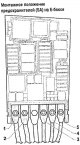
Fuses — mounting position and loading
1. Fuse holder (panel) C-SC- 2. Holder (panel) of fuses B-SB- 3. Fuse holder (panel) A-SA- Loading fuses Loading fuses, since November 2012. Fuses installed, since May 2013. Fuse colors 50 A - red 40 A - orange/green 30...
1. Fuse holder (panel) C-SC- 2. Holder (panel) of fuses B-SB- 3. Fuse holder (panel) A-SA- Loading fuses Loading fuses, since November 2012. Fuses installed, since May 2013. Fuse colors 50 A - red 40 A - orange/green 30...
Relay — design description and loading positions
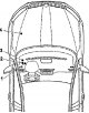
1. Relay bracket on the on-board network control unit holder: on the on-board network control unit holder 2. Relay bracket under the instrument panel to the left: under the instrument panel to the left 3. Relay bracket...
1. Relay bracket on the on-board network control unit holder: on the on-board network control unit holder 2. Relay bracket under the instrument panel to the left: under the instrument panel to the left 3. Relay bracket...

Points of attachment to the mass
Overview of ground connection points in the engine compartment 1. Flexible tape for connection to ground, battery - body "1" 2. Ground connection point on gearbox "14" 3. Ground connection point 3 on the longitudinal...
Overview of ground connection points in the engine compartment 1. Flexible tape for connection to ground, battery - body "1" 2. Ground connection point on gearbox "14" 3. Ground connection point 3 on the longitudinal...
This section is available on russian, bulgarian, belarusian, ukrainian, serbian, croatian, romanian, polish, slovak, hungarian
Read similar sections on other Skoda models
➧ Electrical equipment: Equipment and devices Skoda Fabia 2 (2007-2014)
➧ Electrical equipment: Equipment and devices Skoda Rapid 1 (2012-2022)
➧ Electrical equipment: Equipment and devices Skoda Superb 2 (2008-2015)
➧ Electrical equipment: Equipment and devices Skoda Kodiaq 1 (2016-2024)
➧ Electrical equipment: Equipment and devices Skoda Yeti (2009-2017)
➧ Electrical equipment: Equipment and devices Skoda Felicia (1994-2001)
Link to this section in various formats
TEXTHTMLBB Code
- General information
- User manual
- Car driving
- Maintenance
- Petrol engines 1.2 l
- Engine repair
- Cooling system
- Supply system
- Petrol engines 1.4 l
- Engine repair
- Supply system
- Petrol engines 1.8/2.0 l
- Engine repair
- Cooling system
- Supply system
- Diesel engines 1.6/2.0 l
- Engine repair
- Cooling system
- Supply system
- Transmission
- Mechanical gearbox 02S
- Automatic gearbox 0CW
- Automatic gearbox 0D9
- Chassis (running gear)
- Front suspension
- Rear suspension
- Brake system
- Steering
- Body and interior
- Doors, locks and windows
- Exterior (external elements)
- Interior (internal elements)
- Ventilation and air conditioning
- Electrical equipment
- Equipment and devices
- Headlights and lighting
- Wiring diagrams (basic)
- Wiring diagrams (comfort)
- General information
- Vehicle details
- Maintenance
- Power unit
- Petrol engines 1.6 l AEE
- Petrol engines 1.8 l AGN
- Diesel engines 1.9 l AGR
- Fuel system
- Exhaust system
- Cooling system
- Transmission
- Clutch
- Car gearbox
- Gearbox repair 02J
- Gearbox repair 02K
- Chassis (running gear)
- Wheels and tires
- Suspension and axles
- Brake system
- Body and interior
- Exterior (external elements)
- Interior (internal elements)
- Doors, locks and windows
- Electrical equipment
- Equipment and devices
- Electrical circuits