



Gasoline engines 1.8 and 2.0 liters of a car Skoda Octavia 3


Engine number
The engine number ("engine letter designation" and "serial number") are located on the left near the engine/gearbox junction "arrow". Additionally, on the upper casing of the timing chain there is a sticker with the...
The engine number ("engine letter designation" and "serial number") are located on the left near the engine/gearbox junction "arrow". Additionally, on the upper casing of the timing chain there is a sticker with the...

Removal the engine
Note: The engine is removed downwards together with the gearbox. All bandages that are released or cut when removing the engine must be reinstalled in the same places when installing the engine. When performing...
Note: The engine is removed downwards together with the gearbox. All bandages that are released or cut when removing the engine must be reinstalled in the same places when installing the engine. When performing...

Disconnecting the engine from the gearbox
Cars with MKH 02S The power unit is removed and secured to the bracket for the engine "T10359". Remove the starter. Release the wire harnesses -1 and 2- secured to the air duct. Loosen the screw clamp "4". Unscrew the...
Cars with MKH 02S The power unit is removed and secured to the bracket for the engine "T10359". Remove the starter. Release the wire harnesses -1 and 2- secured to the air duct. Loosen the screw clamp "4". Unscrew the...

Engine installation
Tightening torques Note: Tightening torques are given for lightly greased or oiled, phosphated or oxidized bolts and nuts. Additional lubricants are permitted (for example, motor or transmission oils), except...
Tightening torques Note: Tightening torques are given for lightly greased or oiled, phosphated or oxidized bolts and nuts. Additional lubricants are permitted (for example, motor or transmission oils), except...

Powertrain mounts for vehicles with manual transmission — general installation diagram
1. Engine support bracket 2. Bolt: replacement 3. Engine support: with bracket 4. 40 Nm + turn 90° (¼ turn): replacement 5. 20 Nm + turn 90° (¼ turn): replacement 6. Bracket: coolant check valve 7.8 Nm 8. 60 Nm + turn...
1. Engine support bracket 2. Bolt: replacement 3. Engine support: with bracket 4. 40 Nm + turn 90° (¼ turn): replacement 5. 20 Nm + turn 90° (¼ turn): replacement 6. Bracket: coolant check valve 7.8 Nm 8. 60 Nm + turn...

Engine Mount Bracket — Torque and Tightening Sequence
Note: Replace screws that are tightened to the specified angle. Tighten the screws in several stages in the following order.
Note: Replace screws that are tightened to the specified angle. Tighten the screws in several stages in the following order.

Removal and installation the lower support of the power unit
Note: Replace screws that are tightened to the specified angle. Tighten the screws in several stages in the following order. Remove the noise-insulating casing. Unscrew screws -1, 2, 3- and remove the lower support of...
Note: Replace screws that are tightened to the specified angle. Tighten the screws in several stages in the following order. Remove the noise-insulating casing. Unscrew screws -1, 2, 3- and remove the lower support of...

Powertrain mounts for vehicles with DSG automatic transmission — general installation diagram
1. Engine support bracket 2. Bolt: replace 3. Engine support: with bracket 4. 40 Nm and turn 90° (¼ turn): replace 5. 20 Nm and turn 90° (¼ turn): replace 6.8 Nm 7. Bracket 8. 60 Nm and turn 90° (¼ turn): replace 9....
1. Engine support bracket 2. Bolt: replace 3. Engine support: with bracket 4. 40 Nm and turn 90° (¼ turn): replace 5. 20 Nm and turn 90° (¼ turn): replace 6.8 Nm 7. Bracket 8. 60 Nm and turn 90° (¼ turn): replace 9....

Removal and installation engine mounts
Remove the cover of the drainage box. Remove the engine cover. Disconnect the "2" connector. Unscrew the bolt "1". Remove the "3" hose from the adsorber. Remove the retainers with an arrow screwdriver and set the...
Remove the cover of the drainage box. Remove the engine cover. Disconnect the "2" connector. Unscrew the bolt "1". Remove the "3" hose from the adsorber. Remove the retainers with an arrow screwdriver and set the...

Removal and installation the engine support bracket
Remove the engine mount. Using the "MP9-200/10" "1" hook, lift the engine to a distance of "a". Size "A" = approximately 30 mm. Unscrew bolts -1, 2, 3- and remove the engine support bracket. Installation Installation is...
Remove the engine mount. Using the "MP9-200/10" "1" hook, lift the engine to a distance of "a". Size "A" = approximately 30 mm. Unscrew bolts -1, 2, 3- and remove the engine support bracket. Installation Installation is...

Removal and installation of gearbox supports
Remove the battery with bracket "1". Remove the engine control unit "J623" from the bracket. Unscrew the nuts "arrows" and remove bracket "1". Note: Depending on the modification, the brackets may differ. Remove cable...
Remove the battery with bracket "1". Remove the engine control unit "J623" from the bracket. Unscrew the nuts "arrows" and remove bracket "1". Note: Depending on the modification, the brackets may differ. Remove cable...

Checking the position and adjusting the power unit supports
Checking the position of the power unit supports The following dimensions must be maintained: between engine support "1" and engine bracket there must be a distance "a" = 10 mm; the cast edge of the engine mount bracket...
Checking the position of the power unit supports The following dimensions must be maintained: between engine support "1" and engine bracket there must be a distance "a" = 10 mm; the cast edge of the engine mount bracket...

Parts and units of the drive using a poly V-belt
1. Poly V-belt: check for wear: before removing, mark the direction of rotation with chalk or a felt-tip pen (installing a used poly V-belt with the wrong direction of rotation can lead to its destruction); don't overdo...
1. Poly V-belt: check for wear: before removing, mark the direction of rotation with chalk or a felt-tip pen (installing a used poly V-belt with the wrong direction of rotation can lead to its destruction); don't overdo...

Torque and sequence of tightening the bracket of mounted units
Insert the bracket for the attachments and first screw in bolt "4" by hand. Note: Replace screws that are tightened to the specified angle. Tighten the bolts in sequence -1...5- in 3 stages as follows. 1. Tighten the...
Insert the bracket for the attachments and first screw in bolt "4" by hand. Note: Replace screws that are tightened to the specified angle. Tighten the bolts in sequence -1...5- in 3 stages as follows. 1. Tighten the...

Removal and installation a poly V-belt
Remove the noise-insulating casing. Remove the front right fender liner. Caution! Risk of damage due to reverse running direction of a used poly V-belt. Before removing the poly V-belt, mark its running direction with...
Remove the noise-insulating casing. Remove the front right fender liner. Caution! Risk of damage due to reverse running direction of a used poly V-belt. Before removing the poly V-belt, mark its running direction with...

Removal and installation the tension roller of the poly V-belt
Remove the poly V-belt from the tensioner. Unscrew the screws "arrows" and remove the tensioner "1" of the poly V-belt from the bracket of the attachment units. Installation is in reverse order. Install the poly V-belt.
Remove the poly V-belt from the tensioner. Unscrew the screws "arrows" and remove the tensioner "1" of the poly V-belt from the bracket of the attachment units. Installation is in reverse order. Install the poly V-belt.

Removal and installation the bracket for mounted units
Drain the coolant. Remove the poly V-belt. Remove the three-phase alternator. Disconnect connector "1" from the electromagnetic clutch of the air conditioning compressor. Caution! Do not open the air conditioning system...
Drain the coolant. Remove the poly V-belt. Remove the three-phase alternator. Disconnect connector "1" from the electromagnetic clutch of the air conditioning compressor. Caution! Do not open the air conditioning system...

Removal and installation the crankshaft poly V-belt pulley
Remove the poly V-belt. Using the "T10355" stop, turn the crankshaft poly V-belt pulley to the "TDC cylinder 1" "arrow" position. The notch on the crankshaft poly V-belt pulley should be located opposite the arrow mark...
Remove the poly V-belt. Using the "T10355" stop, turn the crankshaft poly V-belt pulley to the "TDC cylinder 1" "arrow" position. The notch on the crankshaft poly V-belt pulley should be located opposite the arrow mark...

Parts and assemblies of the crankshaft and flywheel cover
1. Dual mass flywheel: installation is only possible in one position - the holes are offset 2. Centering sleeve 3. Flange cover on the gearbox side: with integrated sealing ring; replace only as a set; do not lubricate...
1. Dual mass flywheel: installation is only possible in one position - the holes are offset 2. Centering sleeve 3. Flange cover on the gearbox side: with integrated sealing ring; replace only as a set; do not lubricate...

Removal and installation a dual mass flywheel
The gearbox is removed. Remove the clutch. The engine is installed Insert the stop -MP1-223 (3067)- into the hole in the cylinder block. Stop installation position A. For tightening B. For turning away The engine has...
The gearbox is removed. Remove the clutch. The engine is installed Insert the stop -MP1-223 (3067)- into the hole in the cylinder block. Stop installation position A. For tightening B. For turning away The engine has...

Removal and installation the flange sealing gasket on the gearbox side
Gearbox removed. Remove dual mass flywheel. Remove intermediate plate from crankshaft cover on gearbox side and from centering bushings "arrows". Unscrew screws -1...6-. Press the crankshaft cover from the gearbox side....
Gearbox removed. Remove dual mass flywheel. Remove intermediate plate from crankshaft cover on gearbox side and from centering bushings "arrows". Unscrew screws -1...6-. Press the crankshaft cover from the gearbox side....

Balance shaft parts and components
1. 4 Nm and turn 45° (1/8 turn): replace 2. Balance shaft: exhaust side; after removal replace; lubricate the support with engine oil 3. Needle bushing: Only the same color needle bushing can be used 4. Balance shaft...
1. 4 Nm and turn 45° (1/8 turn): replace 2. Balance shaft: exhaust side; after removal replace; lubricate the support with engine oil 3. Needle bushing: Only the same color needle bushing can be used 4. Balance shaft...


Removal and installation the balance shaft of the intake camshaft
The engine is removed. Remove the toothed belt of the coolant pump drive. Remove the upper timing chain cover. Remove the lower timing chain cover. Remove the camshaft drive chain. Remove the balance shaft drive chain....
The engine is removed. Remove the toothed belt of the coolant pump drive. Remove the upper timing chain cover. Remove the lower timing chain cover. Remove the camshaft drive chain. Remove the balance shaft drive chain....

Replacing the sealing ring of the balance shaft of the intake camshaft
Remove the toothed belt of the coolant pump drive. Unscrew bolt "2". Remove toothed pulley "1" of the coolant pump. Firmly press screwdriver "1" to plane "2" of sealing ring "arrow B". Hook and remove sealing ring...
Remove the toothed belt of the coolant pump drive. Unscrew bolt "2". Remove toothed pulley "1" of the coolant pump. Firmly press screwdriver "1" to plane "2" of sealing ring "arrow B". Hook and remove sealing ring...

Removal and installation the balance shaft of the exhaust camshaft
The engine is removed. Remove the upper timing chain cover. Remove the lower timing chain cover. Remove the camshaft drive chain. Remove the balance shaft drive chain. Unscrew the screw "1" of the inlet camshaft balance...
The engine is removed. Remove the upper timing chain cover. Remove the lower timing chain cover. Remove the camshaft drive chain. Remove the balance shaft drive chain. Unscrew the screw "1" of the inlet camshaft balance...

Timing chain casing parts and assemblies
1. 4 Nm and turn further by 45° (1/8 turn) 2. Valve 1 of the exhaust valve timing adjuster "N318" and valve 1 of the valve timing adjuster "N₂05" 3. Lip seals: replace 4. Upper timing chain cover 5. Gasket: replace if...
1. 4 Nm and turn further by 45° (1/8 turn) 2. Valve 1 of the exhaust valve timing adjuster "N318" and valve 1 of the valve timing adjuster "N₂05" 3. Lip seals: replace 4. Upper timing chain cover 5. Gasket: replace if...

Removal and installation valve timing control valves «N205» / «N318»
Disconnect connector "1" from valve 1 of the exhaust valve timing adjuster "N318" "2" and connector "3" from valve 1 of the valve timing regulator "N₂05" "4". Unscrew the "arrow" screws and remove valve 1 of the valve...
Disconnect connector "1" from valve 1 of the exhaust valve timing adjuster "N318" "2" and connector "3" from valve 1 of the valve timing regulator "N₂05" "4". Unscrew the "arrow" screws and remove valve 1 of the valve...

Removal and installation the upper timing chain cover
Cold engine. Release residual pressure in the cooling system by briefly opening the "arrow" cap on the expansion tank of the cooling system. Remove the engine casing. Open clamp "1", remove the cooling system hose and...
Cold engine. Release residual pressure in the cooling system by briefly opening the "arrow" cap on the expansion tank of the cooling system. Remove the engine casing. Open clamp "1", remove the cooling system hose and...

Removal and installation the lower timing chain cover
Remove the front right mudguard. Remove the engine support bracket. Remove the poly V-belt tensioner roller. Remove the poly V-belt pulley from the crankshaft. Caution! To avoid damaging the toothed ring, screw in the...
Remove the front right mudguard. Remove the engine support bracket. Remove the poly V-belt tensioner roller. Remove the poly V-belt pulley from the crankshaft. Caution! To avoid damaging the toothed ring, screw in the...

Replacing the sealing ring of the crankshaft poly V-belt pulley
Remove the poly V-belt pulley from the crankshaft. Screw back the crankshaft poly V-belt pulley mounting screw using the "T10368" drift. Warning! Risk of engine damage. Do not turn the crankshaft from the TDC position...
Remove the poly V-belt pulley from the crankshaft. Screw back the crankshaft poly V-belt pulley mounting screw using the "T10368" drift. Warning! Risk of engine damage. Do not turn the crankshaft from the TDC position...

Parts and components of the camshaft drive chain
Note: After working with chain drives, adjust the chain length. 1. 4 Nm and turn 90° (¼ turn): replace 2. Chain tensioner: is under spring tension; before removing, lock with the "T40267" lock 3. Timing chain tensioner...
Note: After working with chain drives, adjust the chain length. 1. 4 Nm and turn 90° (¼ turn): replace 2. Chain tensioner: is under spring tension; before removing, lock with the "T40267" lock 3. Timing chain tensioner...

Removal and installation the camshaft drive chain
Remove the upper timing belt cover. Remove the noise-insulating cover. Caution! Regulator valves have left-hand threads. Using the "T10352/2" tool, remove the regulator valves in the "direction of the arrow". Unscrew...
Remove the upper timing belt cover. Remove the noise-insulating cover. Caution! Regulator valves have left-hand threads. Using the "T10352/2" tool, remove the regulator valves in the "direction of the arrow". Unscrew...

Balance shaft drive chain parts and components
1. Guide bolt, 20 Nm 2. Tensioner bar: for the purpose of driving the camshaft 3. Balance shaft: exhaust side; replace after removal; lubricate the support with engine oil 4. Guide bolt, 20 Nm 5. Stabilizer bar: balance...
1. Guide bolt, 20 Nm 2. Tensioner bar: for the purpose of driving the camshaft 3. Balance shaft: exhaust side; replace after removal; lubricate the support with engine oil 4. Guide bolt, 20 Nm 5. Stabilizer bar: balance...

Removal and installation the balance shaft drive chain
Remove the camshaft drive chain, Unscrew the screws "arrows". Remove the balance shaft drive chain tensioner "1". Remove the damper "3". Remove the balance shaft drive chain. Installation Turn the intermediate shaft...
Remove the camshaft drive chain, Unscrew the screws "arrows". Remove the balance shaft drive chain tensioner "1". Remove the damper "3". Remove the balance shaft drive chain. Installation Turn the intermediate shaft...

Checking the valve timing
Remove the upper timing chain cover. Remove the noise-insulating cover. Turn the crankshaft pulley using the "T10355" stop in the direction of the arrow so that the "arrow" marks are almost at the top position. Unscrew...
Remove the upper timing chain cover. Remove the noise-insulating cover. Turn the crankshaft pulley using the "T10355" stop in the direction of the arrow so that the "arrow" marks are almost at the top position. Unscrew...

Cylinder head
Note: Replace the cylinder head screws. During installation work, the self-locking nuts and screws that are tightened by turning to a specified angle, as well as the sealing rings and gaskets, must be replaced. The...
Note: Replace the cylinder head screws. During installation work, the self-locking nuts and screws that are tightened by turning to a specified angle, as well as the sealing rings and gaskets, must be replaced. The...

Removal and installation of the cylinder head
Note: Attach cable ties to the appropriate locations. Seal the open channels of the intake manifold and exhaust tract with suitable plugs, for example from the plug set for the engine "VAS 6122". Drain the coolant....
Note: Attach cable ties to the appropriate locations. Seal the open channels of the intake manifold and exhaust tract with suitable plugs, for example from the plug set for the engine "VAS 6122". Drain the coolant....

Compression check
The engine oil temperature must be at least 30°C. The battery voltage must be at least 12.7 V. Remove the ignition coils with the power output stages. Disconnect the electrical connectors. 1. For injectors -N30...N33-...
The engine oil temperature must be at least 30°C. The battery voltage must be at least 12.7 V. Remove the ignition coils with the power output stages. Disconnect the electrical connectors. 1. For injectors -N30...N33-...
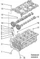
Valve mechanism
Note: The cylinder head and cylinder head cover can only be replaced as a set. After installing the camshafts, the engine must not be started for approximately 30 minutes. The hydraulic clearance compensators must be in...
Note: The cylinder head and cylinder head cover can only be replaced as a set. After installing the camshafts, the engine must not be started for approximately 30 minutes. The hydraulic clearance compensators must be in...

Loosen and tighten the cylinder head cover screws
Unscrewing the cylinder head cover screws Loosen the cylinder head cover screws in sequence -1...6-. Cylinder head cover screw tightening sequence Replace the screws. Note: Make sure that the cylinder head cover is not...
Unscrewing the cylinder head cover screws Loosen the cylinder head cover screws in sequence -1...6-. Cylinder head cover screw tightening sequence Replace the screws. Note: Make sure that the cylinder head cover is not...

Oil separator and vacuum pump parts and components
1. Cylinder head 2. O-ring: replace; lubricate with motor oil 3. Camshaft adjuster actuator (exhaust camshaft) 4.5 Nm 5. Ball head screw, 9 Nm: for engine cover 6. O-ring: replace; lubricate with motor oil 7. Plug 8....
1. Cylinder head 2. O-ring: replace; lubricate with motor oil 3. Camshaft adjuster actuator (exhaust camshaft) 4.5 Nm 5. Ball head screw, 9 Nm: for engine cover 6. O-ring: replace; lubricate with motor oil 7. Plug 8....

Removal and installation camshafts
Note: Do not modify the mating surfaces on the cylinder head cover below and on the cylinder head above. The camshaft bearings are built into the cylinder head and, accordingly, into the cylinder head cover. Before...
Note: Do not modify the mating surfaces on the cylinder head cover below and on the cylinder head above. The camshaft bearings are built into the cylinder head and, accordingly, into the cylinder head cover. Before...

Installing the ball into the camshaft coupling
Warning! Risk of eye injury when the ball pops out! Insert spring "1" into the camshaft. Install ball "2" on the camshaft spring. Using spacer "T40191/1" press the ball with the spring down in the direction of arrow "A"...
Warning! Risk of eye injury when the ball pops out! Insert spring "1" into the camshaft. Install ball "2" on the camshaft spring. Using spacer "T40191/1" press the ball with the spring down in the direction of arrow "A"...

Removal and installation oil seals with the cylinder head installed
Remove the camshafts. For reinstallation, mark the roller rocker arms and hydraulic compensators. If necessary, remove the roller tappet levers together with the hydraulic compensators and set aside on a clean surface....
Remove the camshafts. For reinstallation, mark the roller rocker arms and hydraulic compensators. If necessary, remove the roller tappet levers together with the hydraulic compensators and set aside on a clean surface....

Parts and assemblies of the oil pan and oil pump
Note: If, during engine repair, a large amount of metal shavings and wear products are found in the engine oil, it is necessary to thoroughly clean the oil channels, oil nozzles and additionally replace the oil...
Note: If, during engine repair, a large amount of metal shavings and wear products are found in the engine oil, it is necessary to thoroughly clean the oil channels, oil nozzles and additionally replace the oil...

Oil pan mounting screw tightening sequence
Tightening order of the screws securing the lower part of the oil pan, made of plastic Note: Replace screws that are tightened to the specified angle. Tighten screws -1 through 20- in 2 stages in the sequence shown. 1....
Tightening order of the screws securing the lower part of the oil pan, made of plastic Note: Replace screws that are tightened to the specified angle. Tighten screws -1 through 20- in 2 stages in the sequence shown. 1....
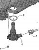
Removal and installation the oil level and temperature sensor «G266»
The engine oil is drained. Disconnect connector "3". Unscrew nuts "1" and remove the oil level and temperature sensor "G266" "4". Installation Installation in reverse order. Note: Replace sealing ring "2". Fill the...
The engine oil is drained. Disconnect connector "3". Unscrew nuts "1" and remove the oil level and temperature sensor "G266" "4". Installation Installation in reverse order. Note: Replace sealing ring "2". Fill the...

Removal and installation the lower part of the oil pan
The engine oil has been drained. Remove the oil level and temperature sensor "G266". For vehicles with a lower part of the oil pan made of plastic Unscrew bolts -1...20-. Remove the lower part of the oil pan. For...
The engine oil has been drained. Remove the oil level and temperature sensor "G266". For vehicles with a lower part of the oil pan made of plastic Unscrew bolts -1...20-. Remove the lower part of the oil pan. For...

Removal and installation the oil pump
Remove the lower part of the oil pan. Unscrew the screw "arrow" and remove the flow shut-off device. Remove the chain tensioner spring using the "T10118" tool in the "direction of the arrow" and lock it using the...
Remove the lower part of the oil pan. Unscrew the screw "arrow" and remove the flow shut-off device. Remove the chain tensioner spring using the "T10118" tool in the "direction of the arrow" and lock it using the...

Removal and installation the upper part of the oil pan
Gearbox removed. Remove lower part of oil pan. Remove crankshaft cover from gearbox side. Remove oil pump. Disconnect connector "1". Pos. "2" can be ignored. Unscrew the "arrow" screws. Using a sharp spatula, cut the...
Gearbox removed. Remove lower part of oil pan. Remove crankshaft cover from gearbox side. Remove oil pump. Disconnect connector "1". Pos. "2" can be ignored. Unscrew the "arrow" screws. Using a sharp spatula, cut the...

Bracket for mounted units with oil filter and engine oil cooling radiator
1. Mounted unit bracket 2. Gasket: replace 3. Oil filter 4. O-ring: replace; lubricate with motor oil; component of the oil filter -position 3- 5. Oil filter cover, 25 Nm 6. Oil filter outlet fitting: replace 7. Sealing...
1. Mounted unit bracket 2. Gasket: replace 3. Oil filter 4. O-ring: replace; lubricate with motor oil; component of the oil filter -position 3- 5. Oil filter cover, 25 Nm 6. Oil filter outlet fitting: replace 7. Sealing...

Removal and installation the engine oil cooling radiator
Warning! Beware of burns from hot steam and hot coolant. When the engine is hot, the liquid in the cooling system is under pressure. When opening, cover the expansion tank cap with a rag and carefully unscrew it. Drain...
Warning! Beware of burns from hot steam and hot coolant. When the engine is hot, the liquid in the cooling system is under pressure. When opening, cover the expansion tank cap with a rag and carefully unscrew it. Drain...

Removal and installation a mechanical distribution valve
Remove the engine oil cooler. Remove the mechanical distribution valve "1" from the bracket of the attachments "arrow". Installation Installation in reverse order. Note: Gaskets and sealing rings must be replaced....
Remove the engine oil cooler. Remove the mechanical distribution valve "1" from the bracket of the attachments "arrow". Installation Installation in reverse order. Note: Gaskets and sealing rings must be replaced....

Parts and components of the crankcase ventilation system
1. Cylinder head cover 2. Gasket: replace 3. Hose: to the electromagnetic valve 1 of the container with activated carbon "N80" 4. Oil separator 5. O-ring: replace 6. Hose: for crankcase ventilation system; to the...
1. Cylinder head cover 2. Gasket: replace 3. Hose: to the electromagnetic valve 1 of the container with activated carbon "N80" 4. Oil separator 5. O-ring: replace 6. Hose: for crankcase ventilation system; to the...

Removal and installation the oil separator
Remove the ignition coils of cylinders "3" and "4". Loosen the clamp "1" and disconnect the hose from the electromagnetic valve 1 of the adsorber "N80". Unscrew the screw "2" and remove the hose "3" of the engine...
Remove the ignition coils of cylinders "3" and "4". Loosen the clamp "1" and disconnect the hose from the electromagnetic valve 1 of the adsorber "N80". Unscrew the screw "2" and remove the hose "3" of the engine...

Oil pressure sensor parts and components
1. 4 Nm and turn 90° (¼ turn): replace 2. Oil pressure regulating valve "N428" 3. O-ring: replace; lubricate with motor oil 4. O-rings: replace; lubricate with motor oil 5. 4 Nm + turn 45° (⅛ turn): replace 6. Control...
1. 4 Nm and turn 90° (¼ turn): replace 2. Oil pressure regulating valve "N428" 3. O-ring: replace; lubricate with motor oil 4. O-rings: replace; lubricate with motor oil 5. 4 Nm + turn 45° (⅛ turn): replace 6. Control...

Removal and installation the control valve for the oil nozzles for cooling the pistons «N522»
Disconnect the "arrow" connector from the piston cooling oil nozzle regulating valve "N522". Unscrew the screw "1" and remove the piston cooling oil nozzle regulating valve "N522" "2". Installation Installation in...
Disconnect the "arrow" connector from the piston cooling oil nozzle regulating valve "N522". Unscrew the screw "1" and remove the piston cooling oil nozzle regulating valve "N522" "2". Installation Installation in...

Removal and installation oil sensors
Removal and installation the oil pressure sensor "F22" Disconnect the "arrow" connector from the oil pressure sensor "F22". Unscrew the oil pressure sensor "F22" "1". Installation Installation in reverse order. Note:...
Removal and installation the oil pressure sensor "F22" Disconnect the "arrow" connector from the oil pressure sensor "F22". Unscrew the oil pressure sensor "F22" "1". Installation Installation in reverse order. Note:...

Removal and installation the oil pressure control valve «N428»
Remove the poly V-belt. Place the oil collection pan "VAS 6208" under the engine. Disconnect connector "1". Unscrew screw "2" and remove the oil pressure regulating valve "N428". Installation Installation in reverse...
Remove the poly V-belt. Place the oil collection pan "VAS 6208" under the engine. Disconnect connector "1". Unscrew screw "2" and remove the oil pressure regulating valve "N428". Installation Installation in reverse...
This section is available on russian, bulgarian, belarusian, ukrainian, serbian, croatian, romanian, polish, slovak, hungarian
Read similar sections on other Skoda models
➧ Petrol engines 1.4 l: Engine repair Skoda Fabia 2 (2007-2014)
➧ Power unit: Engine in car Skoda Favorit (1987-1994)
Link to this section in various formats
TEXTHTMLBB Code
- General information
- User manual
- Car driving
- Maintenance
- Petrol engines 1.2 l
- Engine repair
- Cooling system
- Supply system
- Petrol engines 1.4 l
- Engine repair
- Supply system
- Petrol engines 1.8/2.0 l
- Engine repair
- Cooling system
- Supply system
- Diesel engines 1.6/2.0 l
- Engine repair
- Cooling system
- Supply system
- Transmission
- Mechanical gearbox 02S
- Automatic gearbox 0CW
- Automatic gearbox 0D9
- Chassis (running gear)
- Front suspension
- Rear suspension
- Brake system
- Steering
- Body and interior
- Doors, locks and windows
- Exterior (external elements)
- Interior (internal elements)
- Ventilation and air conditioning
- Electrical equipment
- Equipment and devices
- Headlights and lighting
- Wiring diagrams (basic)
- Wiring diagrams (comfort)
- General information
- Vehicle details
- Maintenance
- Power unit
- Petrol engines 1.6 l AEE
- Petrol engines 1.8 l AGN
- Diesel engines 1.9 l AGR
- Fuel system
- Exhaust system
- Cooling system
- Transmission
- Clutch
- Car gearbox
- Gearbox repair 02J
- Gearbox repair 02K
- Chassis (running gear)
- Wheels and tires
- Suspension and axles
- Brake system
- Body and interior
- Exterior (external elements)
- Interior (internal elements)
- Doors, locks and windows
- Electrical equipment
- Equipment and devices
- Electrical circuits