
Ball joint replacement
1. Remove the hub bolt (see Section 2 of Chapter 8).
2. Remove the front wheel.
3. Give nuts (see illustration 4.5 of chapter 8).
4. Slightly pull the drive shaft out of the hub. If equipped, separate the front suspension height sensor rod from the suspension arm (see Section 8).
5. Pull the ball joint out of the front suspension arm by pulling the steering knuckle out. If necessary, pull the lever down as far as possible.
6. Give a nut of fastening of a spherical support to a rotary fist, having left it screwed on some turns. Install puller #3287A as indicated on Ref. illustration, and press the ball joint out of the steering knuckle. Finally give a nut and remove a spherical support.
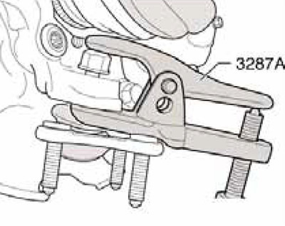
4.6 Removing the ball joint from the steering knuckle
7. Installation is carried out in the reverse order. The right and left supports are different from each other; for identification, they are marked accordingly "R" And "L". Make sure that the ball joint boot is not twisted. When tightening the hub bolt, follow the sequence outlined in Section 2 Chapter 8.
Removing the lever and its support bracket
8. Remove the front wheel.
9. Remove the sound insulation under the engine compartment (see chapter 11).
10. If equipped, separate the front suspension height sensor rod from the suspension arm (see Section 8).
11. Give nuts (see illustration 4.5 of chapter 8) and separate the ball joint from the front suspension arm.
12. Replace the support bracket bolts on both sides in turn with T10096 centering pins (see illustration 3.3 or positions 1 and 8 in illustration 3.11), by tightening them with a force of no more than 20 Nm. Then unscrew the bolts (17 and 10 in illustration 3.11).
13. Turn out bolts (1 in illustration 3.3) and remove the suspension arm along with the bracket.
14. Install the lever with the support bracket on the subframe and screw in the bolts (10 and 17 in illustration 3.11), but do not completely tighten them.
15. Tighten the bolts (1 in illustration 3.3) and a new bolt instead of the centering pin T10096.
16. Tighten the fasteners of the lever on the ball joint and tighten the bolts (10 and 17 in illustration 3.11).
17. Further installation is carried out in the reverse order. Use new fasteners.