
Mounting the steering mechanism on the car (without amplifier)
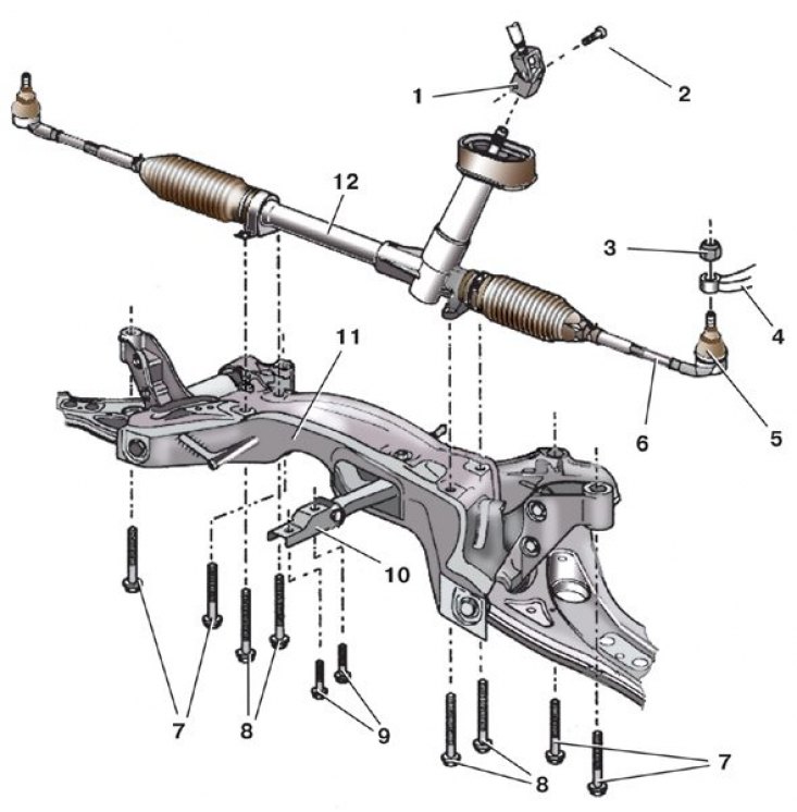
1 - fork cardan joint; 2 - coupling bolt; 3 - nut; 4 - rotary lever; 5 – a tip of steering draft assembled with a spherical hinge; 6 - locknut; 7 – bolts of fastening of a beam of a forward suspension bracket; 8 – bolts of fastening of the steering mechanism; 9 – bolts of fastening of a back support of the power unit; 10 - rear support of the power unit; 11 – front suspension beam; 12 - steering gear
Vypressovka of a finger of a spherical hinge of a tip of steering draft
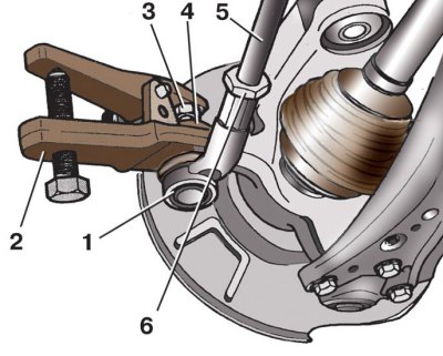
1 - tip; 2 - puller; 3 - nut; 4 - rotary lever; 5 - thrust; 6 - locknut
Steering draft assy
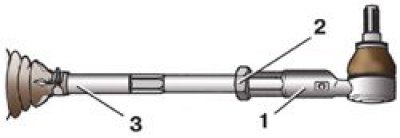
1 - tip; 2 - locknut; 3 - thrust
Marking of tie rod ends
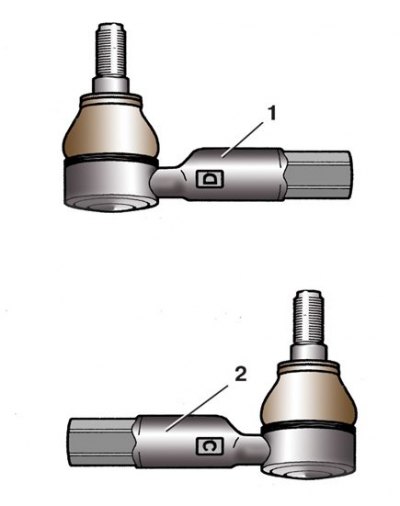
1 - left tip; 2 - right tip
Examination
1. With increasing free play (backlash) steering wheel or a significant increase in the effort required to turn it, check the axial and radial clearances in the ball joints of the tie rod ends.
2. If, when shaking the rod by hand in different directions, play is felt in the joint or corrosion appears on the ball pin, replace the ball joint assembly with the tip (check with the front wheels off).
3. Be sure to replace the torn protective cover of the ball joint, otherwise dirt and water that have entered the joint will quickly disable it.
Attention! The ball joint pin nuts are self-locking and must be replaced with new ones after each loosening.
Replacement
1. Remove the corresponding wheel.
2. Clean locknut 6 (see fig. Mounting the steering mechanism on the car (without amplifier)) tie rod end and ball joint pin nut 3.
3. Loosen the lock nut 6 of the tip, holding the hexagon rod from turning with the second wrench.
4. Turn away a nut 3 fingers of a spherical hinge.
5. Install puller 2 (see fig. Vypressovka of a finger of a spherical hinge of a tip of steering draft) and press the ball joint pin out of the pivot arm.
6. If for some reason the rod from the rotary lever is disconnected without replacing the tip 1, then, depending on the design of the puller, leave the fastening nut 3 screwed on several turns on the hinge pin so as not to damage its thread.
7. Disconnect the steering rod 5 from the pivot arm 4.
8. Unscrew tip 1 (see fig. Steering draft assy), while holding the hexagon rod 3 from turning. At the same time, count the number of revolutions of the tip - this will help when installing the tip to approximately maintain the toe-in of the wheels.
Attention! When installing, note that the left handpiece is marked with the letter D, and the right handpiece is marked with C (see fig. Marking of tie rod ends).
9. Screw tip 1 (see fig. Steering draft assy) on the tie rod 3 by the previously calculated number of revolutions.
10. Press the pivot pin into the pivot arm 4 (see fig. Mounting the steering mechanism on the car (without amplifier)), screwing a new nut 3 of its fastening with the appropriate moment (if necessary, the finger can be kept from turning with a hexagon).
11. After that, fix the tip 5 on the steering rod with a lock nut 6, holding the steering rod from turning by the hexagon.
12. Install the wheel.
13. Check and, if necessary, adjust the wheel alignment.
Tightening torques, Nm
| Ball joint pin nut | 20, then turn 90° |
| Tip locknut | 50 |
| Wheel bolts | 120 |