



Petrol models 1.8 and 2.0 l: coolant lines and coolant temperature sensor "G62" (ECT)
1. The details of the installation of the coolant lines are shown in the accompanying illustration. Removal and installation of individual lines is not considered. The following describes the removal / installation of the ECT sensor.
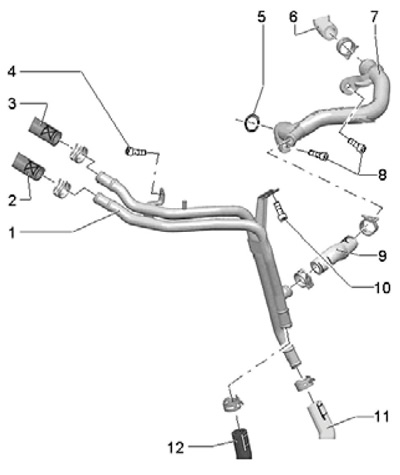
7.1 Coolant lines for 1.8 and 2.0 l petrol engines
1 Coolant pipes (front)
2 Coolant hose, from turbocharger
3 Coolant hose, to expansion tank
4, 10 Bolt, 5 Nm
5 Sealing ring, subject to replacement
6 Coolant hose, to the heater radiator
7 Small coolant pipe
8 Bolts, 9 Nm
9 Coolant hose
11 Coolant hose, from pump "V51"
12 Coolant hose, to pump "V51"
2. Follow the steps described in paragraphs 9-12 of Section 6.
3. Remove the throttle body module "J338" (see Chapter 4).
4. Loosen the nut (2 in illustration 6.18), unscrew the bolt (1) and remove the intake manifold support.
5. Disconnect the connector (1 in illustration 4.30) eCT sensor "G62", squeeze the clamp tabs (arrows), pull it out and remove the ECT sensor.
6. Installation is performed in the reverse order. Use a new sensor sealing ring. Finally, adjust the coolant level.
Diesel models 2.0 l (cFFB, CFGB, CLJA engines)
7. Details of the installation of sensors, coolant lines and coolant circulation pump No.2 "V178" are shown in the accompanying illustration.
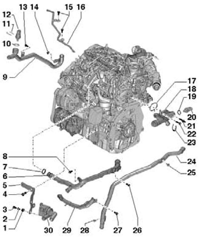
7.7 Installation details of sensors, coolant lines and coolant circulation pump No.2 "V178"
1 Gasket, not supplied separately
2 Bushing, not supplied separately
3 Bolt, 3 Nm
4 Bolt, 40 Nm
5 Pump support 30
6 Front coolant pipe
7, 10, 19 Sealing ring, subject to replacement
8 Bolt, 8 Nm
9 Right coolant pipe
11, 23 Retainer
12 Sensor "G83" coolant temperature at the radiator outlet
13, 15, 22 Bolt, 9 Nm
14 Nut, 9 Nm
16 Upper coolant pipe
17 Gasket, subject to replacement
18 Cylinder head connection
20 Sensor ECT "G62"
21 Stud bolt, 9 Nm
24 Left coolant pipe
25-27 Bolt, 9 Nm
28 Bolt, 13 Nm
29 Front Upper Coolant Pipe
30 Coolant circulation pump No.2 "V178"