
Petrol models 3.6 l
1. Details of the installation of the radiator and its fan are indicated on the resist. illustrations.
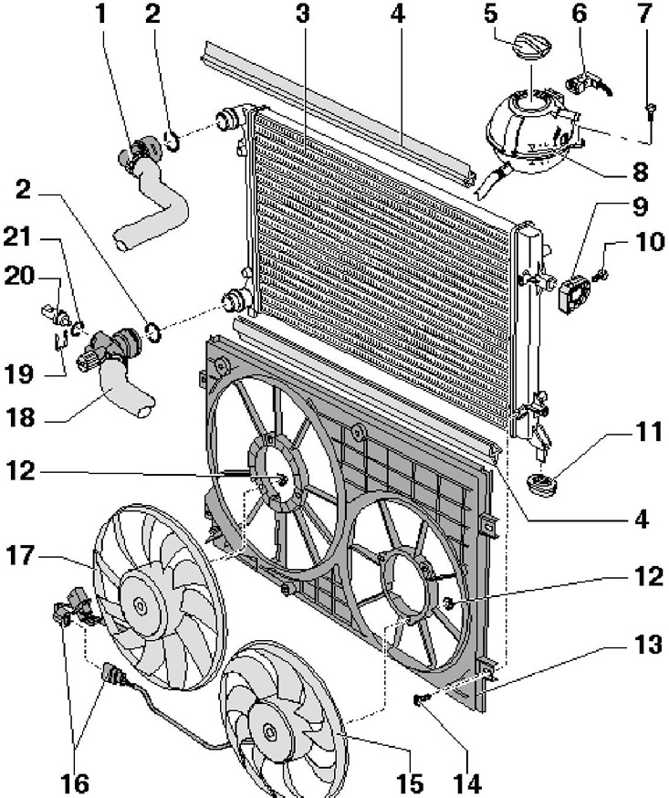
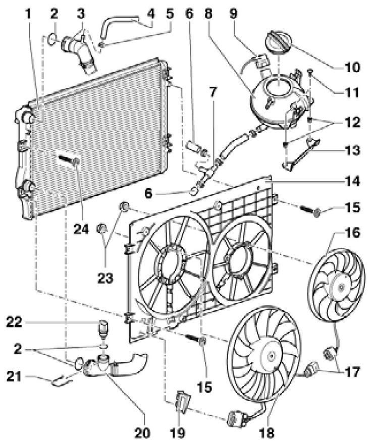
3.1 Installation details of the radiator and its fans on 3.6L models
1 Upper coolant hose, to connection on cylinder head
2 O-ring
3 Radiator, replace coolant after replacement
4 Gasket, not installed
5 Screw cap
6 connector
7 Bolt, 3 Nm
8 Expansion tank, with D/V "G32" low coolant level
9 Radiator supports, installed cut-up
10 Bolt, 7 Nm
11 Support
12 Nut, 5 Nm
13 Fan shroud
14 Bolt, 5 Nm
15 Right fan "V35" radiator
16 Connectors
17 Fan "V7" radiator, with block "J293" fan control
18 Lower coolant hose, to thermostat connection
19 Retainer
20 Sensor "G83" coolant temperature at the radiator outlet
21 O-ring, to be replaced
2. Remove the top two screws securing the fan shroud (arrows in Illustration 15.16 of Chapter 2).
3. Remove the sound insulation under the engine compartment (see chapter 11) and remove the bolts (2 and 3 in Illustration 5.11 of Chapter 2) oscillating support.
4. Disconnect the connector (1 in Illustration 15.16 of Chapter 2) and remove the two lower fan shroud mounting bolts.
5. Have an assistant push the engine as far back as possible and remove the fan shroud towards the rear.
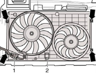
6. Disconnect connectors (1 and 2 on resist. illustrations) and release the wiring. Then give the nuts (arrows) and remove the fan.
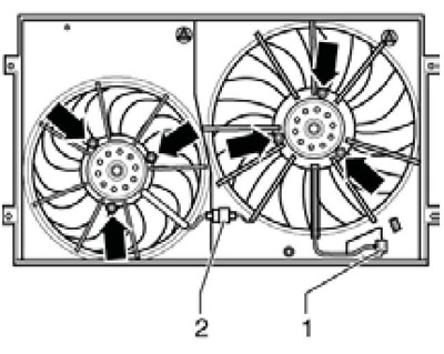
3.6 Fasteners and fan connectors
7. If necessary, after removing the fan shroud, the heatsink can be removed as described below.
8. Blow the coolant (see section 2).
9. Disconnect the sensor connector "G83" coolant temperature at the radiator outlet and tie up the coolant hose at the bottom of the radiator.
10. Remove the front bumper (see chapter 11).
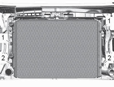
11. Turn out bolts (1 per resist. illustrations) radiator mountings. Note: Do not open the refrigerant circuit and do not overstretch, kink or twist the refrigerant lines.
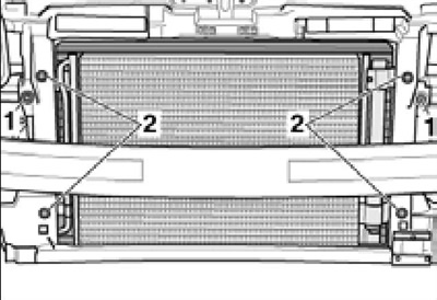
3.11 Capacitor fixing (2) and radiator (1)
12. Ask an assistant to pull the radiator back, remove its supports on the sides and pull it out of the lower supports.
13. Loosen the bottom bolts of the condenser (see resist. illustration) and remove the radiator downwards.
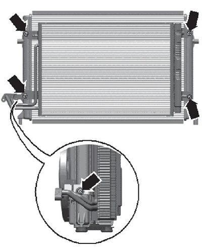
3.13 Capacitor fixing
14. Installation is carried out in the reverse order.
Petrol models 1.4 l
15. Details of the installation of the radiator and its fans are indicated on the resist. illustrations.
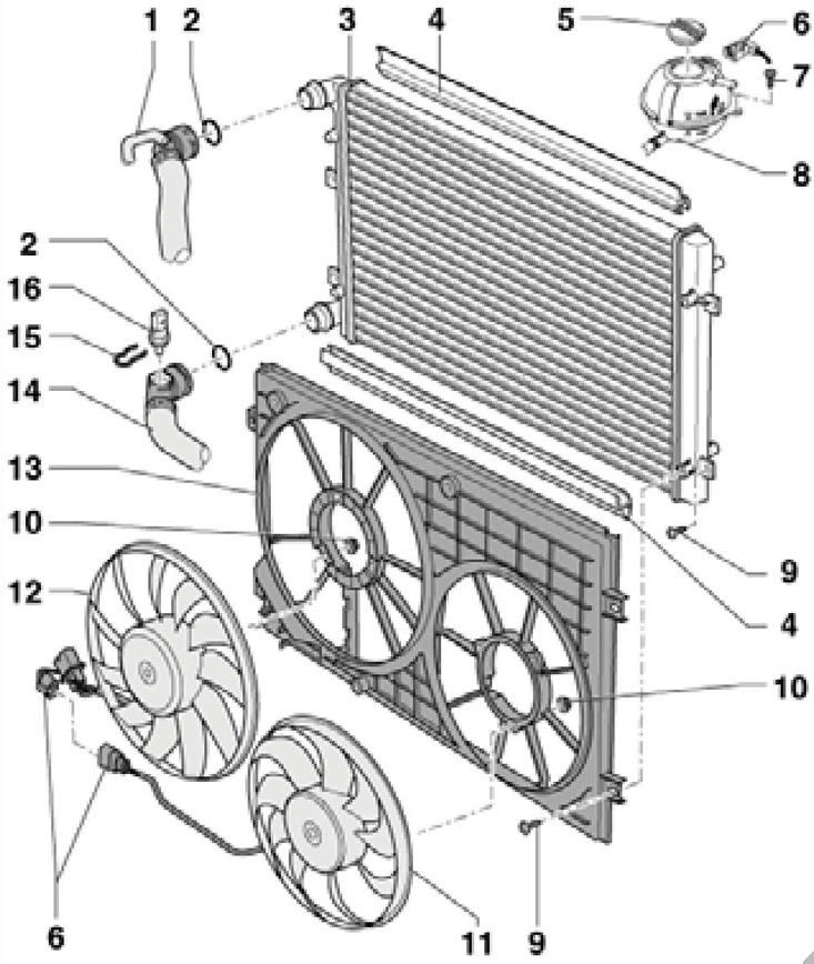
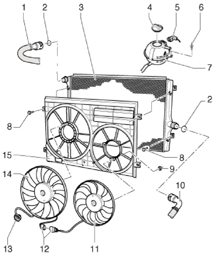
3.15 Installation details of the radiator and its fans on 1.4 l models
1 Radiator
2 O-ring, to be replaced
3 Upper coolant hose, to cylinder head
4 Coolant hose, to expansion tank
5 Spring clamp
6 Coolant hose, to coolant pipe for intercooler radiator
7 Connecting tube
8 Expansion tank, with sensor "G32" low coolant level
9, 17 Wiring connector
10 Tank cap 8
11 Bolt, 3 Nm
12 Plastic inserts, for bolts
13 Support
14 Fan shroud
15 Bolt, 5 Nm
16 Right fan "V35" radiator
18 Fan "V7" radiator, with control unit "J293"
19 Connector holder
20 Lower coolant hose, to thermostat housing
21 Retainer
22 Sensor "G83" coolant temperature at the radiator outlet
23 Nut, 5 Nm
24 Intercooler radiator bolt, 5 Nm
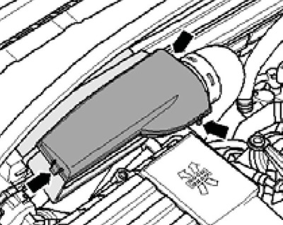
16. To remove the fan shroud, you must remove the air cleaner (see chapter 4). The casing and fans are removed in the same way as on the 3.6L engine (see paragraphs 2-6), however, it is not necessary to remove the oscillating bolts, but remove the cover downwards (no need to push the engine back).
17 The radiator can only be removed after the fan shroud has been removed and the cooling system has been emptied. To remove the radiator, it is enough to disconnect the hoses from it and unscrew the 4 bolts of its fastening. The radiator is removed downwards.
Petrol models 1.8 and 2.0 l
18. Details of the installation of the radiator and its fans are indicated on the resist. illustrations. To remove the fan shroud, follow the steps described in paragraphs 19-21. To remove the heatsink, go to paragraph 22.
3.18 Installation details of the radiator and its fans on petrol models 1.8 and 2.0 l
1 Upper coolant hose, to coolant pump
2 O-ring
3 Radiator, replace coolant after replacement
4 Gasket, to be replaced
5 Tank cap 8
6 Wiring connector
7 Bolt, 3 Nm
8 Expansion tank, with sensor "G32" low coolant level
9 Bolt, 5 Nm
10 Nut, 10 Nm
11 Right fan "V35" radiator
12 Fan "V7" radiator, with control unit "J293"
13 Fan shroud
14 Lower coolant hose, to thermostat housing
15 Retainer
16 Sensor "G83" coolant temperature at the radiator outlet
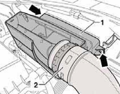
19. Press the latches (see resist. illustration) and remove the connection cover.
3.19 Connection cover locks
20. Remove bolts (arrows on resist. illustrations) connections (1) and remove the connecting hose (2) from the guide.
3.20 Fixing the connection
21. Turn out the top bolts of a casing of fans (arrows on resist. illustrations), remove the sound insulation under the engine compartment (see chapter 11), disconnect the connector (1), unscrew the bottom bolts of the casing and remove it downwards.
3.21 Fixing the fan shroud
22. Cool down (see section 2).
23. Disconnect the connector (2 in Illustration 23.19 of Chapter 2) and remove the fan shroud (see paragraphs 19-21).
24. Disconnect the coolant hoses from the top and bottom of the radiator.
25. Remove the bolts (1 and 2 on resist. illustrations) and lift the radiator down.
3.25 Radiator fixing
Diesel models 2.0 l (motors CFFB, CFGB, CLJA)
26. Details of the installation of the radiator and its fans are indicated on the resist. illustrations.
3.26 Installation details of the radiator and its fans
1 Upper coolant hose, to cylinder head
2 O-ring, to be replaced
3 Radiator
4 Tank cap 7
5, 12, 13 Connector
6 wiring harness Bolt, 3 Nm
7 Expansion tank, with sensor "G32" low coolant level
8 Bolt, 5 Nm
9 Nut, 5 Nm
10 Lower coolant hose, to 4/2-way valve and thermostat housing
11 Right fan "V35" radiator
12 Fan "V7" radiator, with control unit "J293"
15 Fan shroud
27. To remove the fan shroud, remove the left air pressure hose (see chapter 4). The casing is removed downwards.
28. The radiator is removed only after removing the fan casing and emptying the cooling system, by analogy with 1.8 and 2.0 l gasoline engines (see above). Disconnect the high refrigerant pressure sensor connector first.