
Petrol models 3.6 l
1. Details of thermostat installation are shown in illustration 4.1.
2. Blow the coolant (see section 2).
3. Set aside the wiring connector (1 per resist. illustrations) aside, remove the coolant hoses from the oil cooler (arrows) and also put them aside.
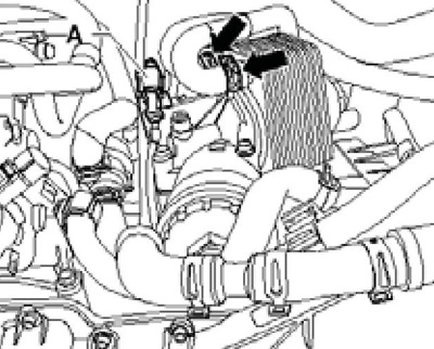
6.3 Oil cooler connections
4. Turn out bolts (see resist. illustration) and remove the thermostat housing together with the hose connected to it. Remove the thermostat from its housing.
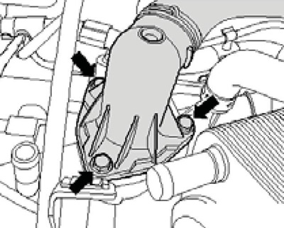
6.4 Bolts for fixing the thermostat housing
5. Clean the seal mating surface and insert the thermostat into its housing, matching the edges (see resist. illustration). Moisten the new thermostat seal with coolant and place it over the thermostat housing joint. Tighten the thermostat housing fasteners to 8 Nm.
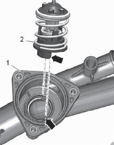
6.5 Installation position of the thermostat in its housing
6. Repair oil cooler connections and add coolant.
Petrol models 1.4 l
7. Details of setting the thermostat of petrol models 1.4 l are indicated on the sopr. illustrations.
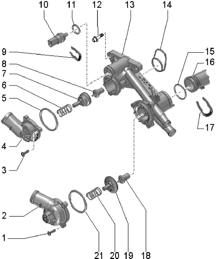
6.7 Installation details of thermostats for petrol engines 1.4 l
1, 3 Bolt, 5 Nm
2, 4 Connection
5, 11, 15, 21 O-ring, to be replaced
6, 20 Spring
7, 19 Pusher, do not tilt when installing
8 Thermocouple thermocouple, adjustable from 105°C to 120°C, stroke min. 8 mm, do not interchange with thermocouple 18
9, 17 Retainer
10 ECT sensor "G62"
12 Self-locking bolt, replaceable, 11 Nm
13 Thermostat housing
14 Gasket, to be replaced
16 Coolant pipe
18 Thermocouple thermocouple, adjustable from 83°C to 98°C, stroke min. 8 mm, do not interchange with thermocouple 8
Petrol models 1.8 l
8. Installation details of the coolant pump and thermostat are shown in illustration 4.18.
9. Blow the coolant (see section 2).
10. Press the latches (see illustration 3.19) and remove the connection cover.
11. Turn out bolts (arrows in illustration 3.20) connections (1) and remove the connecting hose (2) with guide.
12. Push in the tabs (1 and 3 on resist. illustrations) and pull out the connecting hose (4) from the air cleaner (2).
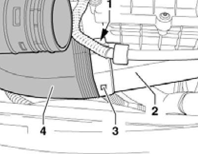
6.12 Separating the connecting hose from the air cleaner
13. Loosen clamp (2 in Illustration 23.16 of Chapter 2), disconnect the connector (arrow) sensor ''G31" boost pressure, remove the bolts (1 and 4) and remove the pressure air tube with a hose from below.
14. Loosen coolant hose (2 in illustration 4.20) and wiring harness (1). Remove the bolt (arrow) and remove the bracket.
15. Remove the bolt (2 in Illustration 23.26 of Chapter 2) on bracket for coolant circulation pump ''V51'".
Remark: Pump "V51" remains in the set position.
16. Disconnect coolant hoses (see illustration 4.22) and put them aside.
17. Give the fasteners of the oil intake and close the hole formed so that dirt does not get into it.
18. Loosen the nut (2 to resist. illustrations), remove the bolt (1) and tilt the intake manifold support slightly to the right.
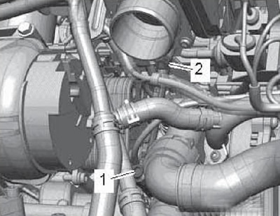
6.18 Fixing the intake pipe support
19. Turn out bolts (see resist. illustration) and remove the thermostat housing. Remove the thermostat.
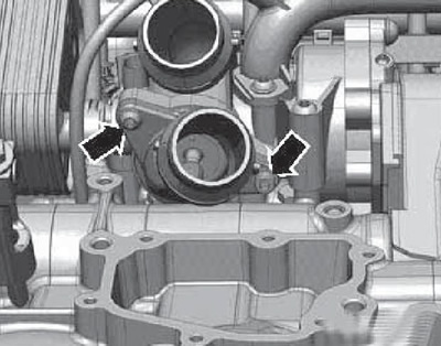
6.19 Fixing the thermostat housing
20. Prepare new O-rings and gaskets. Clean the sealing surface and moisten the new O-rings with coolant.
21. Insert thermostat (4 to resist. illustrations) into the coolant pump housing (5) and slightly tilt forward in the direction of the arrow. Establish a connection carefully (3), by inserting a centering pin (2) into the guide (1).
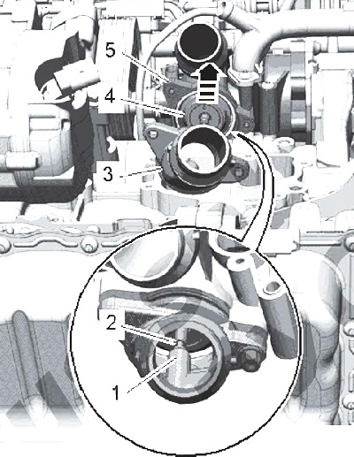
6.21 Setting the thermostat
22. Further installation is carried out in the reverse order.
Diesel models 2.0 l (motors CFFB, CFGB, CLJA)
23. Installation details of the coolant pump and 4/2-way valve with thermostat are shown in illustration 4.33.
24. To remove the 4/2-way valve and thermostat assembly:
- bleed the coolant (see section 2);
- remove air cleaner with MAF sensor and intake hose (see chapter 4);
- remove the battery and its holder (see chapter 5);
- remove the left pressure air tube;
- disconnect the coolant hoses;
- remove the right pressure air tube;
- Remove the guide tube for the engine oil level dipstick.