
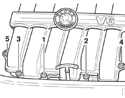
Engine 3.6 l
Note: The following describes the removal of the upper part of the intake piping; its lower part is removed together with the fuel distribution line (see Section 9).
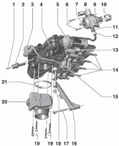
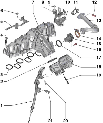
1. Details of the installation of the inlet pipeline are indicated on the resist. illustrations.
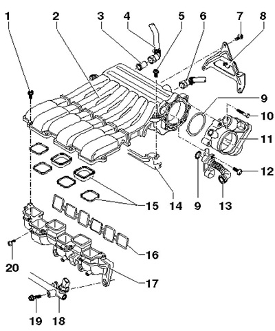
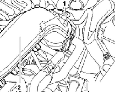
7.1 Details of installation of the inlet pipeline (engine 3.6 l)
1 Captive bolt, 10 Nm
2 Upper part of the intake pipe
3 sealing sleeve
4 To the vacuum brake booster
5 Bolt, 10 Nm
6 To e / m valve No. 1 adsorber EVAP
7 Bolt, 20 Nm
8 Rear intake manifold support, on the protective screen
9 O-ring, to be replaced
10 Bolt, 7 Nm
11 Throttle valve module
12 Bolt, 3.5 Nm
13 PCV connection, from cylinder head cover, with heating resistor "N79"
14 Front intake manifold support, on the cylinder head
15 Gasket, to be replaced, installed dry in part 2 and then lightly lubricated with engine oil
16 Gasket, to be replaced
17 Lower part of the inlet pipeline
18 Fuel distribution line for cylinders No. 2, 4, 6
19 Bolt, to be replaced, 30 Nm, then retighten 90°
20 Bolt, 8 Nm
2. Disconnect the connectors of the electrical wiring of the ignition coils (see chapter 5), wring out the cable channel with a screwdriver and set the connectors aside (see resist. illustration).
7.2 Separating the cable duct
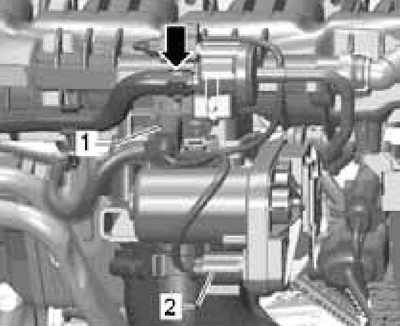
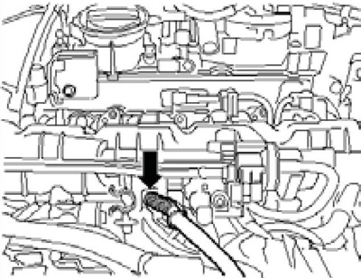
3. Disconnect the connector (1 per resist. illustrations), remove the inlet hose (2) and pull out the connecting PCV hose (3) from the cylinder head cover.
7.3 Removing the PCV hose
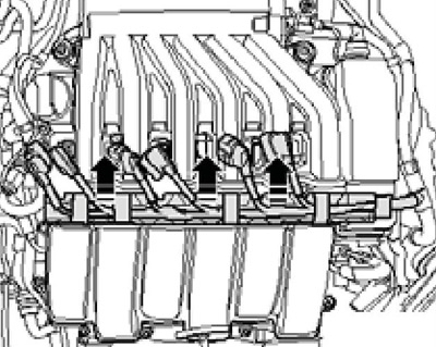
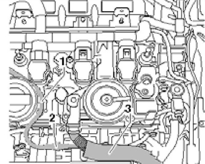
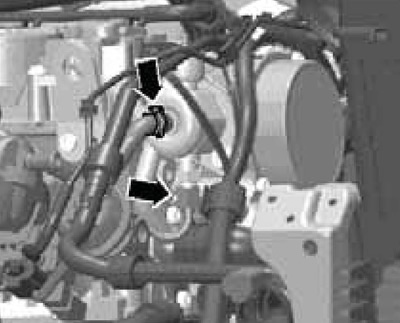
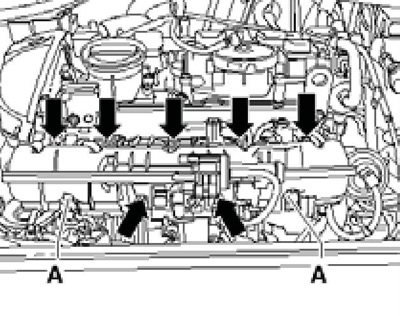
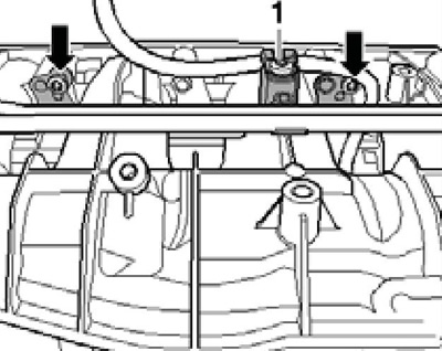
4. Disconnect the hoses from the top of the intake manifold (arrows), remove the bolt (1) back support and bolts (2) front intake manifold support.
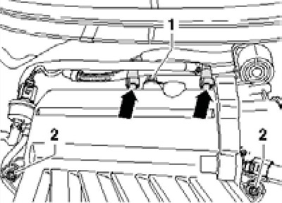
7.4 Connections and fixings for intake pipe supports
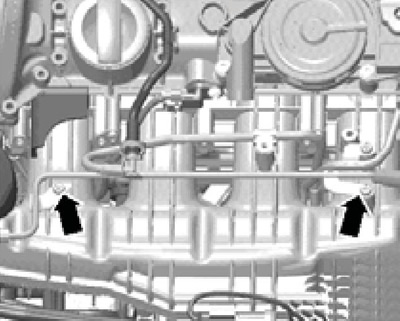
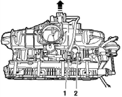
5. Turn out bolts of fastening of the top part of the inlet pipeline to its bottom part and remove the top part (see resist. illustration). Plug the intake ports to keep dirt out.
7.5 Fastening the upper part of the inlet pipe
6. Insert new dry pads (15 in illustration 7.1) into the top of the intake manifold, and then lightly lubricate them with engine oil.
7. Further installation is carried out in the reverse order. Tighten the bolts in the sequence shown in illustration 7.5.
Engine 1.4 l
8. Details of installation of the inlet pipeline and throttle valve module are indicated on the resp. illustrations. Removing the upper part of the intake piping is possible only after removing the throttle valve module, and removing the lower part of the intake piping is possible only after removing its upper part.
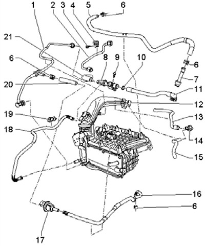
7.8a Inlet pipe connections (engine 1.4 l, part 1)
1, 18 20 Connecting hose
2 High pressure fuel pipe, 18 Nm (on injection pump) and 20 Nm (at the bottom of the intake manifold)
3.9 Bolt, 8 Nm
4, 19 holder
5 Low pressure fuel hose, to injection pump
6 Spring clip
7 Connection, for fuel line
8 Non-return valve PCV
10 O-ring, to be replaced
11 Connection, on timing case
12 Pressure pipe, from turbocharger
13 Connecting hose, on timing case
14 Non-return valve
15 Connecting hose, on the air cleaner
16 Connecting hose, on EVAP canister
17 Solenoid valve No. 1 "N80" EVAP
21 Connecting hose, on turbocharger
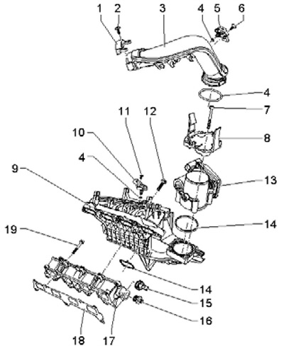
7.8b Inlet piping installation details (engine 1.4 l, part 2)
1 holder
2, 7 Bolt, 7 Nm
3 Pressure tube
4, 14 O-ring, to be replaced
5 Sensor "G31" boost pressure with IAT sensor No. 2 "G299"
6, 11 Bolt, 5 Nm
8 adapter
9 Upper section of intake manifold, with intercooler
10 Sensor "G71" intake manifold pressure and IAT sensor "G42"
12, 19 Bolt, 20 Nm
13 Module "J338" throttle body, ECM adaptation required after replacement
15 Sensor "G247" fuel pressure, 22 Nm
16 80 Nm
17 Lower part of the inlet pipeline
18 Gasket, to be replaced
9. Remove the key from the ignition switch. Remove the engine top cover.
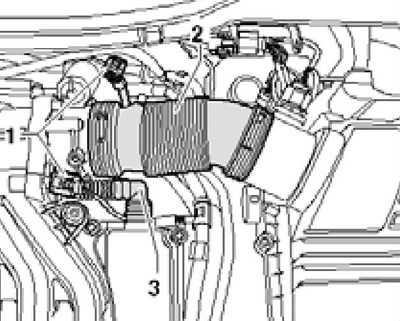
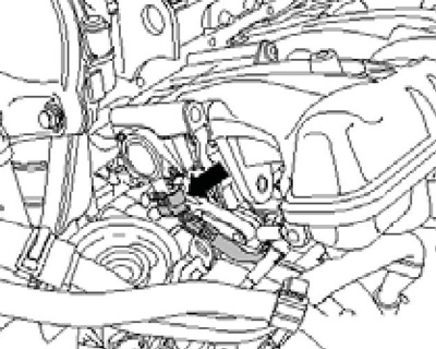
10. Separate the hoses from the pressure tube (1 and 2). Disconnect the boost pressure sensor connector "G31", combined with sensor No. 2 IAT "G299" (4) and remove the screws (3).
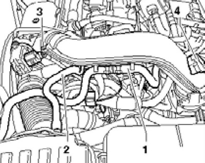
7.10 Pressure tube hoses, sensor connector and screws (3)
11. Release the latches (1 per resist. illustrations), slightly pull the pressure pipe up and separate it from the turbocharger.
7.11 Removing the pressure pipe
12. Disconnect the connector (1 per resist. illustrations) throttle module (3), remove the bolts (2) and remove it from the intake manifold. If necessary, remove the intake manifold as described in paragraphs 13-15.
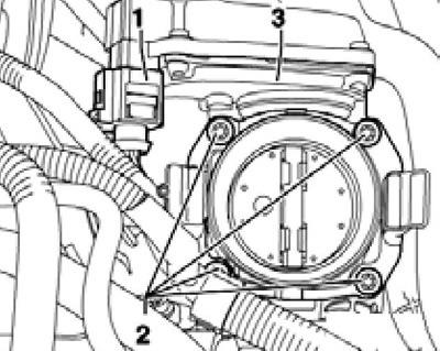
7.12 Removing the throttle valve module
13. Drain the coolant from the intercooler circuit (see chapter 3).
14. Remove the fuel supply line (2 in Illustration 23.20 of Chapter 2), by collecting escaping fuel with a cloth.
15. Remove coolant hoses (1 per resist. illustrations), disconnect the connectors (2), remove the fuel supply line (3) and remove the bolts (4) intake manifold fittings.
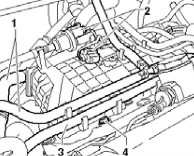
7.15 Removing the top section of the intake manifold
16. Installation of the inlet pipeline is made upside-down. Bolts of fastening of the inlet pipeline tighten with effort of 20 Nm. Finally, fill and bleed the engine cooling system (see chapter 3). When installing the throttle module, pay attention to the following points.
17. If necessary, clean the throttle valve module as described in paragraphs 18-19. Install a newer throttle module into the groove in the intake manifold.
18. Open the removed throttle valve by hand and lock it in the open position with a wooden or plastic wedge (see resist. illustration), so as not to scratch it.
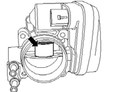
7.18 Locking the damper in the open position
19. Thoroughly clean the throttle module with acetone (according to DIN 53247) and brushes, paying particular attention to the cylindrical surface mating with the shutter.
Caution: Acetone is extremely flammable. When cleaning, do not use compressed air, wear safety goggles and gloves.
Wipe the throttle body with a lint-free cloth and let the acetone evaporate completely.
20. If a new throttle module or new ECM is installed, clear the adapted values and re-learn the ECM to the throttle module using a scan tool (see chapter 5). The adaptation can only be carried out with a new or cleaned throttle valve module, as deposits at the end of the damper stroke can lead to incorrect adaptation values.
Petrol engines 1.8 and 2.0 l
21. Details of installation of the inlet pipeline are specified on sopr. illustrations. To remove the throttle plate only, follow the steps in paragraphs 22-24. The inlet pipeline is removed together with the fuel distributive highway (paragraphs 25-42), after which they can be separated from each other (paragraphs 43-44).
7.21 Details of installation of the inlet pipeline (petrol engines 1.8 and 2.0 l)
1 Sensor bolt 2.5 Nm
2 IAT sensor "G42"
3 Solenoid valve No. 1 "N80" EVAP, with valve 15
4 Inlet pipeline
5 Vacuum block (regulator) for intake manifold flap valve
6 High pressure pump bolts, to be replaced, 10 Nm
7 Fuel line connector from fuel tank
8 Valve "N276" fuel pressure adjustment
9 injection pump, with valve 8
10 Roller pusher
11 Connection for high pressure fuel line, to be replaced, 22 Nm
12 Fuel pipe to fuel distribution line, 18 Nm
13 Control valve "N316" intake manifold flaps
14 Injectors; O-rings and teflon rings must be replaced
15 Double non-return valve, integrated in valve 3
16 Intake manifold support
17 Support bolt 16, 23 Nm
18 Support nut 16, 10 Nm
19 Bolts module 20, 4 pcs., 5 Nm
20 Module "J338" throttle body, ECM adaptation required when replacing
21 Seal, to be replaced
22. Loosen clamp (2 in Illustration 23.16 of Chapter 2), remove the bolt (4) and disconnect the connector (arrow).
23. Remove the sound insulation under the engine compartment (see chapter 11), loosen clamps (1 and 2 in Illustration 7.23 of Chapter 4) and remove the pressure air hose. Remove the bolt (1 in Illustration 23.16 of Chapter 2) and remove the pressure air tube downwards.
24. Disconnect the connector (1 in Illustration 4.29 of Chapter 3), remove the bolts (arrows) and remove the throttle module. The throttle module is cleaned in the same way as on a 1.4 l engine (see above). To install, go to paragraph 45.
25. Remove the air cleaner (see Section 4).
26. Clear connection of the inlet pipeline with a head of cylinders.
27. Disconnect the vacuum line (arrow on resist illustrations), that goes to the EVAP canister, and also disconnect the connectors of the following parts: IAT sensor "G42" (1), module "J338" throttle valve (2), solenoid valve N21 "N80" EVAP and CMP sensor "G40".
7.27 Connections
28. Disconnect the vacuum line (1 per resist. illustrations) at the connecting point (2) and remove the PCV hose (3).
7.28 Vacuum line (1) and PCV hose (3)
29. Remove the bolts (see resist. illustration) fuel feed pipe and set it aside.
7.29 Fuel feed pipe bolts
30. Relieve fuel pressure (see Section 3) and give the union nut of the fuel pipe to the injection pump (lower arrow on resist. illustrations).
7.30 Fuel pipes
31. Disconnect the vacuum tube (see resist. illustration) from the valve "N316" intake manifold flaps.
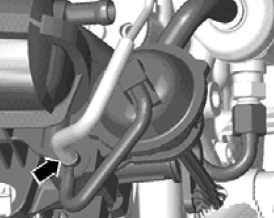
7.31 Vacuum tube on valve N316
32. Remove the coolant pipe mounting bolts from the intake manifold (see Figure 30.24 of Chapter 2).
33. Disconnect the connector (1 in Illustration 30.23 of Chapter 2) sensor "G247" fuel pressure.
34. Loosen the clamps (1 and 2 in Illustration 2.10 of Chapter 3) and remove the charge air hose.
35. Loosen the clamp (2 in Illustration 23.16 of Chapter 2), disconnect the connector (arrow) sensor "G31" boost pressure, loosen the clamp on the pressure air tube, unscrew the bolts (1 and 4) and remove the pressure tube with the hose down.
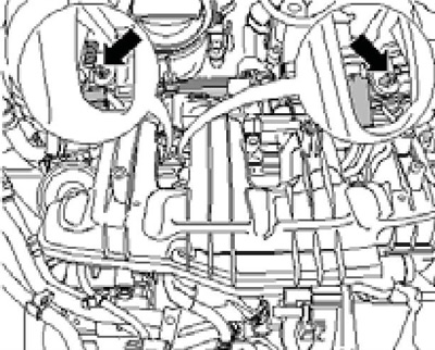
36. Disconnect connectors (1-3 per resist. illustrations) and unscrew the holder from the intake manifold.
7.36 Wiring connectors
37. Give the nut (1 in Illustration 30.25 of Chapter 2), remove the bolt (2) and remove the intake manifold support.
38. Unscrew the oil filter using the N°3417 wrench and cover the oil filter holder to keep dirt out.
39. Loosen the wiring harness holders (see resist. illustration).
7.39 Wiring holder
40. Release the cable from the intake manifold (see resist. illustration).
7.40 Cable on the inlet pipeline
41. Give nuts (And on the opposite illustrations) and loosen the bolts (arrows) inlet pipeline. Gently pull the intake piping together with the fuel rail slightly out of the cylinder head.
7.41 Fixing the intake pipe
42. Disconnect the connector (see resist. illustration) sensor "G336" position of the damper of the inlet pipeline and remove the inlet pipeline. Seal the intake ports with a clean cloth.
7.42 Sensor connector G336
Note: The injectors may remain in the fuel rail.
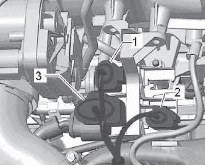
43. Pull out the valve No. 1 from the holder "N80" EVAP (arrow on resist illustrations). Remove double non-return valve (1) and fuel pipe (2).
7.43 Solenoid valve N80 and double non-return valve
44. Loosen the clamp (1 per resist. illustrations) hose, remove both lower bolts (arrows) and pull the fuel rail out of the intake manifold.
7.44 Fuel rail bolts
45. Installation is carried out in the reverse order. Pay attention to the following features.
46. Before installation of assembly of the inlet pipeline and the fuel distributive highway injectors have to be established in a head of cylinders. If during installation the intake manifold was slightly extended again and the injectors remained in the fuel rail, they must be reinstalled in the cylinder head.
47. If a new module is installed "J338", clear the adapted values and re-adapt the ECM to this module using the scan tool. After installing a new intake piping, the sensor "G336" throttle position must be adapted to the ECM.
Diesel engines 2.0 l (CFFB, CFGB and CLJA)
48. Details of the installation of the inlet pipeline are indicated on the resist. illustrations.
7.48 Details of installation of the inlet pipeline of diesel engines 2.0 l (CFFBC, CFGB and CLJA)
1 Engine oil dipstick guide tube
2, 17 O-ring, to be replaced
3, 11 Gasket, to be replaced
4, 16, 19 Bolt, 8 Nm
5 Fuel return line
6, 9, 20 Bolt, 9 Nm
7 Inlet pipeline
8 Valve bracket 10
10 Changeover valve "N345" EGR radiator
12 Bolt, 20 Nm
13 EGR radiator connection pipe
14 Clamp, 5 Nm, to be replaced
15 EGR connection
18 Module "J338" throttle valve, with potentiometer "G69"
21 Tube retainer 1