



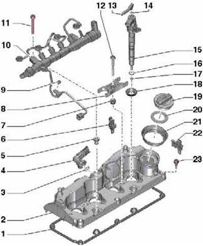
38.1 Cylinder head cover installation details
1 Gasket
2 Cylinder head cover
3, 14, 16 Sealing ring, subject to replacement
4 PCV hose
5 Sealing sleeve for main line bolt 10
6, 22 Wiring Holder
7 Gasket
8 Holder
9 Bolt, 8 Nm
10 Fuel distribution line
11 Bolt, 22 Nm
12 Bolt, to be replaced, 8 Nm, then tighten to an angle of 180°
13 Return fuel line
15 Nozzle
17 Thermal seal, subject to replacement
18 Injector seal, must be replaced
19 Oil filler cap
20 Gasket
21 Lid seal 19
23 Bolt, 10 Nm
2. Remove the top engine cover (see section 34).
3. On CFFB and CFGB engines, disconnect the connector (2 in illustration 36.6) differential pressure sensor "G505", unscrew the bolt (3) and remove the bracket together with the sensor from the bracket of the additional fuel pump in the direction of the arrow. Put the bracket with the sensor aside.
Note: The "G505" sensor is very sensitive, so do not allow it to touch other parts.
4. Press the clamps (see illustration 36.11) and remove the upper timing belt cover.
5. Remove the injectors and fuel rail (see Chapter 4).
6. Remove the PCV hose from the cylinder head cover (1 on the accompanying illustration), by squeezing the locking buttons.
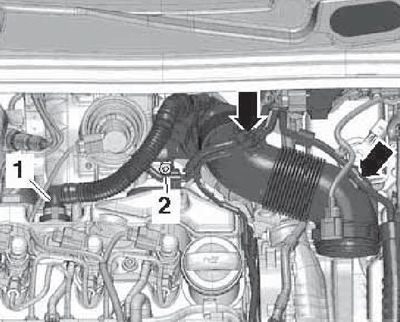
38.6 PCV Hose
7. Disconnect the connector of the G581 boost pressure regulator position sensor (see accompanying illustration). Remove the vacuum lines from the bracket on the cylinder head cover.
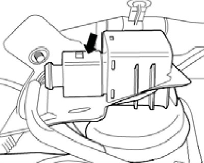
38.7 Sensor connector "G581"
8. Remove the cylinder head cover bolts in the following sequence: (6-1 on the accompanying illustration) and take it off.
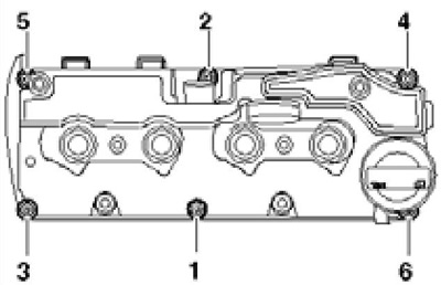
38.8 Cylinder Head Cover Bolt Tightening Sequence
9. Release the cylinder head cover from the holders (see accompanying illustration) on the rear timing belt cover and remove it from the cylinder head.
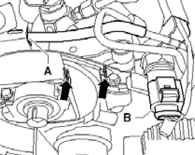
38.9 Cylinder head cover retainers
10. Installation is carried out in the reverse order. If there is a leak, replace the gasket and cylinder head cover mounting bolts, as well as the gaskets and seals of the injectors. Tighten the cylinder head cover mounting bolts in the sequence (1-6 in illustration 38.9) with a force of 10 Nm. Make sure that the cylinder head cover is correctly fixed in the rear timing belt cover (see accompanying illustration). Make sure there is sufficient clearance between the housing and the hub.
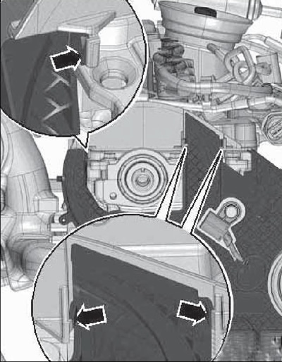
38.10 Position of the cylinder head in the rear timing belt housing