
Note: When removing the cylinder head, the temperature of the engine must not exceed 35°C, otherwise the cylinder head may be deformed after loosening its bolts.
1. Installation details of the cylinder head, vacuum pump and CMP sensor are indicated on the resist. illustrations.
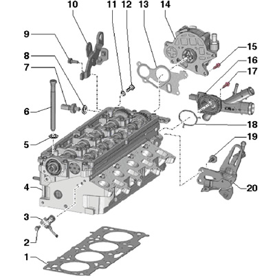
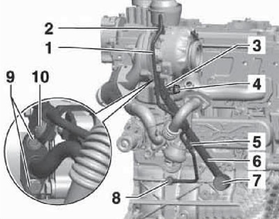
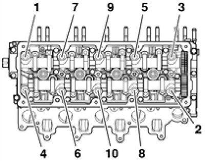
39.1 Installation details of the cylinder head, vacuum pump and CMP sensor
1 Cylinder head gasket, to be replaced
2, 15 Bolt, 10 Nm
3 CMP sensor "G40"
4 Cylinder head
5 Bolt washer 6
6 Cylinder head bolt, to be replaced, insert washers 5 into the cylinder head before tightening
7 D/V "F1" engine oil pressure, with green marking, by 0.5 bar, 22 Nm
8, 11 O-ring, to be replaced
9, 19 Bolt, 20 Nm
10, 20 Lifting eye
12 Oil line screw plug,
14 Nm
13, 18 Gasket, to be replaced
14 Vacuum pump
16 Connection, with ECT sensor
17 Bolt, 10 Nm
2. To replace the CMP sensor, you must remove the timing belt (see Section 36), and then disconnect the sensor connector, unscrew its mounting bolt and release the wiring from the opening by breaking the jumper holders with a screwdriver. When installing, fix the wiring in the opening with a rubber cap from the repair kit.
3. To remove the vacuum pump, remove the air cleaner (see chapter 4), disconnect the vacuum line from the pump, slightly press down the left pressure air tube (to do this, loosen its fasteners) and remove the pump mounting bolts. Use a new vacuum pump seal when installing.
4. Remove the air cleaner together with the MAF sensor "G70" and inlet hose (see chapter 4).
5. Remove the battery and its holder (see chapter 5).
6. Remove the shroud along with the fans "V7" And "V35" radiator (see chapter 3).
7. Remove the cylinder head cover (see Section 38).
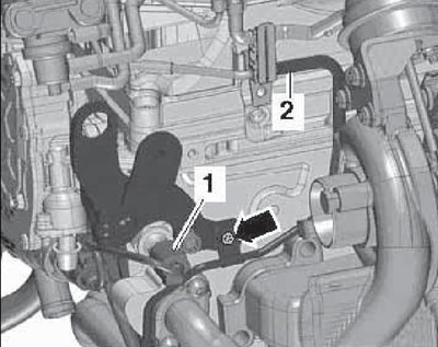
8. Disconnect the connector (2 to resist. illustrations) throttle module, unscrew the probe mounting bolt (4) and disconnect the vacuum line from the vacuum pump.
39.8 Throttle connector (2) and oil dipstick bolt (4)
9. Turn out bolts (2, 5 and arrows on resist. illustrations), release the wiring and hoses on the left pressure air tube, loosen the clamp (3) and remove the left pressure air tube.
39.9 Removing the left air tube
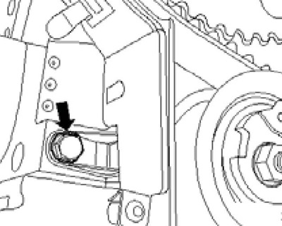
10. Turn out bolts (arrows on resist. illustrations) and remove the pulsation damper (2).

39.10 Bolts (arrows) damper (2)
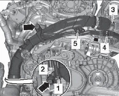
11. Lower the coolant (see chapter 3). Disconnect connector (4 to resist. illustrations) ECT sensor "G62", loosen clamps (1 and 2) and remove the coolant hoses from their fittings.
39.11 Connector (4) ECT sensor and clips (1 and 2) coolant hoses
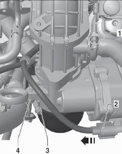
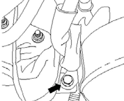
12. Disconnect the connector (1 per resist. illustrations) D/V "F1" engine oil pressure, remove the bolt (arrow) and remove the vacuum hose (2).
39.12 Removing the vacuum hose (2)
13. Remove the wiring connector (3 on resist. illustrations) from the bracket and separate it. Release the wiring lines on the turbocharger.
39.13 Wiring connector (3)
14. Turn out bolts (arrows in illustration 35.7) from the air tube. Release coolant hose (3), loosen clamp (2), disconnect the connector (L) sensor "G31" charge air pressure/IAT sensor "G42" and remove the charge air pipe.
15. Remove EGR connecting pipes (And on the opposite illustrations), using the XZN10 bit. The corrugated part of the connecting tube must not be kinked or overtightened.
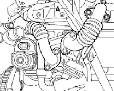
39.15 EGR connecting pipes
16. Give nuts (arrows on resist. illustrations) particulate filter bracket (A) on the cylinder block.
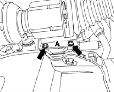
39.16 Nuts particulate filter bracket
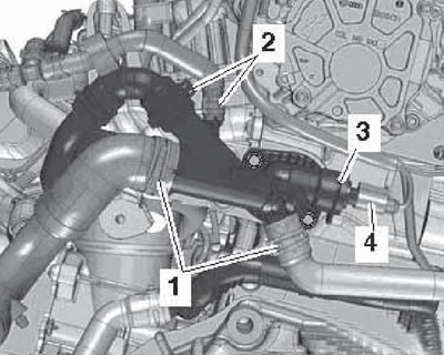
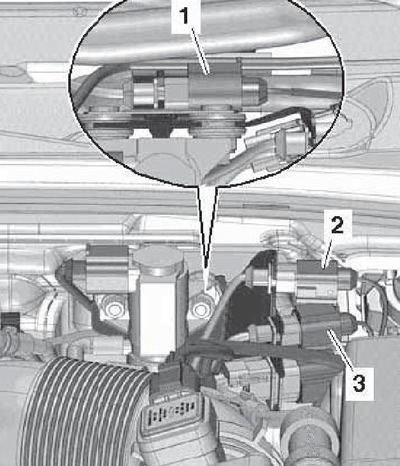
17. Turn out bolts (5 and 10 on resist. illustrations), give the union nut (2) and set aside the oil supply line (1) back. Remove the bolt (4) and remove the bracket (3).
39.17 Removing the bracket (3)
18. Remove the bolt (see resist. illustration) rear timing belt cover, loosen the clamp between the turbocharger and the diesel particulate filter.
39.18 Bolt rear timing belt cover
19. Turn out a bolt from an arm on a head of cylinders (see resist. illustration) and push the particulate filter to the side.
39.19 Cylinder head bracket bolt
20. Disconnect the CMP sensor connector "G40" (see resist. illustration).
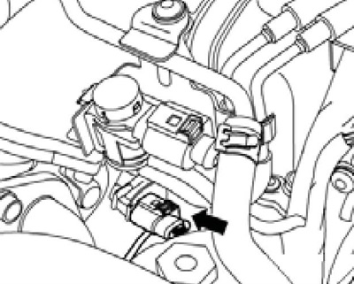
39.20 CMP sensor connector
21. Remove the timing belt from the camshaft (see Section 36).
22. Remove the camshaft gear and its hub using the T10052 puller.
23. Give the timing belt tensioner nut.
24. Turn out bolts of fastening of a head of cylinders in sequence (1-10 per resist. illustrations). Make sure that all hoses, pipes and wiring are disconnected from the cylinder head.
39.24 The sequence of reversing the cylinder head bolts
25. An assistant is required to remove the cylinder head. When the cylinder head is raised, the timing belt tensioner pulley is pulled off the stud and the turbocharger oil return line is pulled out of the support. When removing the cylinder head, first lift it on the transmission side and slide it out of the rear timing belt cover without letting the timing belt tensioner fall. Set the removed cylinder head aside without deforming the oil return pipe. Place a block of wood under the exhaust manifold, if necessary. If the cylinder head is removed with the glow plugs, do not lay it on the lower mating surface.
26. Lay a clean cloth on the cylinder block so that dirt does not get into the oil channels, as well as between the pistons and cylinder walls. Carefully clean the mating surfaces of the cylinder head and cylinder block. Be careful not to damage mating surfaces. The use of a chemical sealant and grease remover is recommended.
27. Determine the deviation of the lower mating surface of the cylinder head from flatness. If this value is more than 0.1 mm, replace the cylinder head. Machining of mating surfaces is not allowed. Clean threaded holes. Make sure that there is no oil or coolant in the threaded holes of the cylinder block, otherwise the cylinder block may crack when the bolts are tightened.
28. Lay a new gasket on the cylinder block so that the part number or label indicated on the gasket "top" were readable.
Note: Do not remove the gasket from the package until you are ready to install the gasket; handle the gasket carefully. The markings on the new gasket must match the markings on the old gasket (see Section 42).
To center the gasket, guide pins MP1-208 or N°3070 can be screwed into the cylinder block (see resist. illustration).
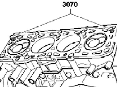
39.28 Guide pins
29. Before installing the cylinder head, remove the T10050 crankshaft fixing tool and turn the shaft counterclockwise so that the pistons are almost equally below TDC.
Note: Do not remove the open valve guards from the new cylinder head before you are ready to install the cylinder head. If a reversible cylinder head is installed, lubricate the mating surfaces of the rocker arms and camshaft cams with engine oil.
30. Install the cylinder head. In this case, the tension roller should go on the hairpin. Screw in new cylinder head bolts by hand, and then tighten them in sequence (10-1 in Figure 39.25) in several stages: first with a force of 30 Nm, then tighten to a force of 50 Nm, and finally tighten by an angle of 180°.
31. Further installation is carried out in reverse order.