



Contents: Removal ⬇ Installation ⬇
1. Timing belt and engine bracket installation details are shown in the accompanying illustration.
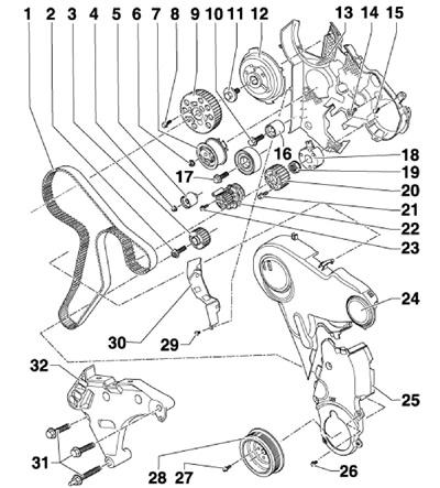
36.1 Timing Belt Installation Details
1 Timing belt
2 Gear mounting bolt
3, subject to replacement, 120 Nm, then tighten to an angle of 90°
3 Crankshaft gear
4 Nut, 20 Nm
5, 16 Intermediate roller
6 Nut, 20 Nm, then tighten to an angle of 45°
7 Tension roller
8 Nut, 20 Nm, then tighten to an angle of 45°
9 Camshaft gear wheel
10 Bolt, 20 Nm
11 Bolt, 100 Nm
12 Wheel hub 9
13 Rear timing belt cover
14 Bolt, to be replaced, 20 Nm, then tighten to an angle of 45°
15 Bolt, subject to replacement, 12 Nm
17 Bolt, to be replaced, 50 Nm, then tighten to an angle of 90°
18 Hub TH BD
19 Nut, 95 Nm
20 Fuel injection pump gear
21 Bolt, to be replaced, 20 Nm, then tighten to an angle of 90°
22 Water pump
23 Bolt, 15 Nm
24 Upper timing belt cover
25 Lower timing belt cover
26 Bolt, 9 Nm, installed on fixing sealant D000 600A2
27 Bolt, to be replaced, 10 Nm, then tighten to an angle of 90°
28 Crankshaft pulley
29 Bolt, 5 Nm
30 Protective plate
31 Bolt, to be replaced, 40 Nm, then tighten to an angle of 180°
32 Engine bracket
Removal
2. Place the transmission in neutral to allow the crankshaft to turn and remove the key from the ignition.
3. Remove the top engine cover (see paragraph 1 of Section 34).
4. Remove the accessory drive belt (see Section 35).
5. Disconnect the feeder (2 in illustration 34.18) and return (1) fuel lines by squeezing the clamps.
6. Disconnect the connector (2 on the accompanying illustration) differential pressure sensor "G505", unscrew the bolt (3) and remove the bracket together with the sensor from the bracket of the additional fuel pump in the direction of the arrow. Put the bracket with the sensor back.
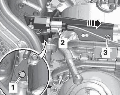
36.6 Differential pressure sensor and its bracket
Note: The "G505" sensor is very sensitive, so do not allow it to touch other parts.
7. Unscrew the bolt (1 in illustration 34.20) and push the neck (2) with the filling tube to the side.
Note: For clarity, the fuel filter is not shown in the illustration.
8. Release the fuel hose (2 in illustration 34.21) from the bracket, remove the fuel line bracket upwards in the direction of the arrow and set it aside. Disconnect the connector (1) of the additional fuel pump "V393" and unscrew the bolts (3). Disconnect the connector of the expansion tank and unscrew its bolts.
9. Loosen the bolt by two turns (1 in illustration 34.22), unscrew the bolt (2) and remove the nut (3). Separate the coolant line bracket from the fuel filter. Place the expansion tank and fuel filter on the engine without disconnecting the hoses from them.
10. Disconnect the connector (3 on the accompanying illustration) coolant temperature sensor "G83" at the radiator outlet. Loosen the nut (1), unscrew the bolt (2) and push aside the right coolant pipe with the hoses connected to it.
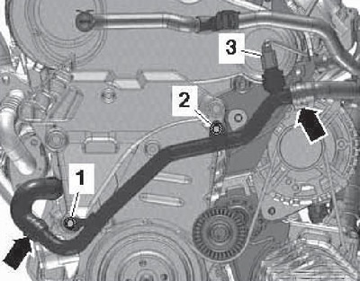
36.10 Right coolant pipe
11. Press the clamps (see accompanying illustration) and remove the upper timing belt cover. Remove the crankshaft pulley (see section 35), without blocking the auxiliary drive belt tensioner.
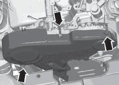
36.11 Timing Belt Upper Cover Fasteners
12. Unscrew the bolts and remove the lower timing belt cover (see accompanying illustration).
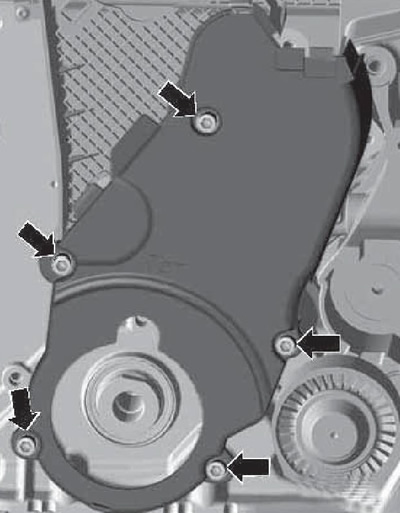
36.12 Fastening the lower timing belt cover
13. Turn the crankshaft clockwise to the TDC position of piston No.1 and fix the crankshaft gear with the T10050 device (see accompanying illustration). When inserting the pin of the T10050 device into the hole in the front sealing flange, the marks on the toothed segment of the device (1) and on the crankshaft toothed wheel (2) must coincide.
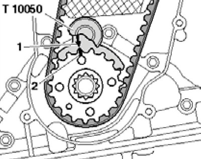
36.13 Fixing the crankshaft at TDC
14. If the belt being removed is to be reused, mark the direction of its rotation on it. Lock the camshaft gear hub with tool N°3359 and loosen the bolts (arrows in the accompanying illustration) gear attachments at approximately 90°.
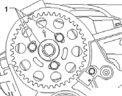
36.14 Camshaft gear mounting bolts
15. Unscrew the bolt (1 on the accompanying illustration) coolant pipes and loosen the bolts (2) securing the fuel injection pump gear by approximately 90°.
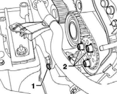
36.15 Fastening of coolant pipe (1) and fuel injection pump gear (2)
16. Loosen the nut (1 on the accompanying illustration) tension roller fastenings and turn its eccentric counterclockwise (arrow) with the T10264 Allen key until the T10265 locking device can be inserted. Lock the tension roller with the T10265 device.
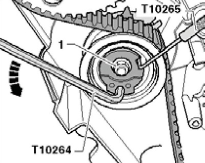
36.16 Tensioner locking
17. Turn the tension roller eccentric clockwise (arrow on the accompanying illustration) until it stops and tighten the nut (1) by hand. Remove the timing belt first from the large idler roller, and then from the remaining rollers and gears.
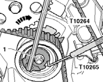
36.17 Removing the timing belt
Installation
Note: The timing belt tension should be adjusted on a cold engine, since the position of the tensioner indicator depends on the engine temperature.
Note: If the tensioner pulley needs to be replaced, the engine bracket must be removed.
18. Make sure that the tension roller is locked with the T10265 device and secured with a nut screwed all the way in (see illustration 36.17).
19. Make sure the crankshaft is locked with the T10050 tool (see illustration 36.13), and the camshaft hub is locked with tool #3359 (see illustration 36.14). Replace the camshaft and fuel injection pump gear mounting bolts one by one. When doing this, screw in the new bolts only by hand, so that the gears can be turned without being skewed.
20. If necessary, turn the fuel injection pump hub using a screwdriver by the bolt heads (1 on the accompanying illustration) enough so that it could be fixed.
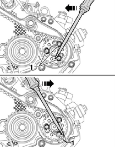
36.20 Turning the fuel injection pump hub
21. Secure the fuel injection pump hub by pushing the locking pin No.3359 into the adjustment hole on the outside of the fuel injection pump gear (see accompanying illustration).
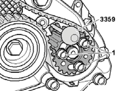
36.21 Fixing the fuel injection pump hub
22. Turn the camshaft gears (3 on the accompanying illustration) and the high-pressure fuel pump (5) in their oblong holes clockwise until they stop. Put the timing belt on the crankshaft toothed wheel (1), pass it through the tension roller (2), the camshaft toothed wheels (3), the water pump (4) and the high-pressure fuel pump (5). Finally, pass the timing belt through the intermediate roller (6).
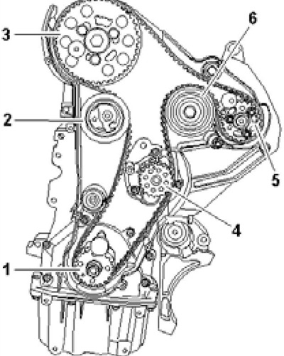
36.22 Timing Belt Routing Diagram
23. Loosen the tension roller nut and pull out the T10265 tool (see illustration 36.17). Make sure the tensioner pulley is seated correctly in the rear timing belt cover (see accompanying illustration).
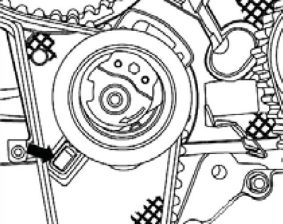
36.23 Position of the tension roller in the rear timing belt cover
24. Install the T10172 counter support with T10172/4 adapters on the camshaft gear and press it in the direction of the arrow (see accompanying illustration) and hold the camshaft gear in the pre-tension position. In this position, tighten the bolts (1) of the camshaft gear, and then the bolts (2) of the injection pump gear with a force of 20 Nm.
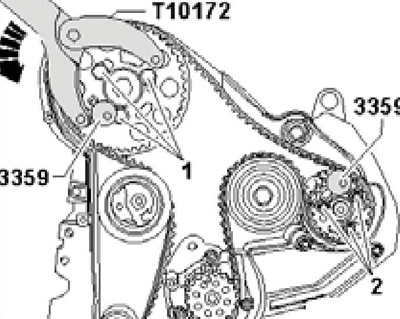
36.24 Tightening the bolts securing the camshaft gears (1) and the high-pressure fuel pump (2)
Note: The bolts should be finally tightened after checking the correct installation of the timing phases (see below).
25. Carefully turn the tension roller eccentric clockwise with the T10264 hexagon until the tension indicator (2 on the accompanying illustration) is in the centre of the gap in the base plate. Make sure that the nut (1) does not turn. Holding the tension roller in this position, tighten its fastening nut with a force of 20 Nm, and then tighten it to an angle of 45°.
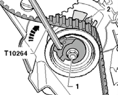
36.25 Tensioning the timing belt
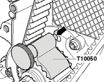
26. Remove the N₂3359 camshaft and fuel injection pump locking pins and the T10050 crankshaft locking pin. Turn the crankshaft 2 turns clockwise, set it to the position just before TDC and install the T10050 crankshaft locking pin. Turn the crankshaft clockwise until the pin (arrow on the accompanying illustration) the T10050 retainer entered the hole in the sealing flange.
36.26 Pin of the T10050 device
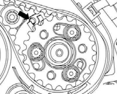
27. When performing the following check procedure, only the camshaft and crankshaft must be fixed. Again, it is quite difficult to find the mounting position of the injection pump hub, but a small deviation (arrow on the accompanying illustration) does not affect engine operation.
36.27 Deviation from fuel injection pump adjustment
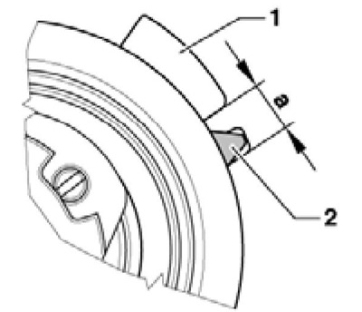
28. Check that the camshaft hub can be secured with locking pin No.3359 and that the indicator (2 on the accompanying illustration) the tension roller is located in area (a) of the base plate (1).
36.28 Position of the indicator before checking the timing phases
29. If the camshaft hub cannot be locked, proceed as described in paragraphs 30-32. Otherwise, proceed to paragraph 33.
30. Pull out the T10050 crankshaft locking tool until the pin comes out of the hole. Turn the crankshaft counterclockwise slightly past the TDC position, and then slowly turn it clockwise until the camshaft hub can be locked with the locking pin #3359. After locking, loosen the camshaft gear mounting bolts on the locked hub.
31. Check the position of the T10050 retainer pin relative to the hole in the sealing flange (see illustration 36.26). If the pin is to the left of the hole, slowly turn the crankshaft clockwise until the pin enters the hole and tighten the camshaft timing gear mounting bolts to 20 Nm.
32. If the pin of the T10050 tool is to the right of the hole, turn the crankshaft slightly counterclockwise (so that the pin is to the left of the hole), and then clockwise until the pin enters the hole. Tighten the camshaft gear mounting bolts to 20 Nm.
33. Remove locking pin No.3359 and crankshaft retainer T10050 and check the timing phases again (see paragraphs 26-29).
34. If the camshaft hub can be fixed, tighten the camshaft gear mounting bolts by an angle of 45°, holding it from turning with the T10172 tool and T10172/4 adapters. Then tighten the fuel injection pump gear mounting bolts by an angle of 90°, holding it from turning with the T10172 tool and T10172/8 adapters.
35. Further installation is carried out in reverse order.