
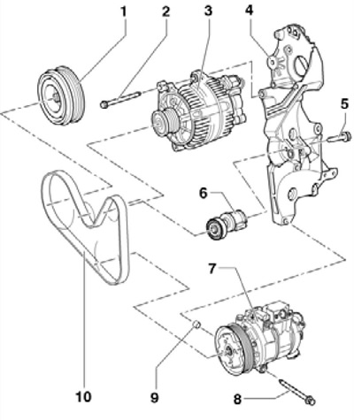
35.1 Accessories drive parts (on the example of models with a compressor)
1 crankshaft pulley
2 Bolt, 25 Nm
3 Generator
4 Auxiliary bracket
5 Bolt, to be replaced, 20 Nm, then retighten 180'
6 Belt tensioner 10
7 Refrigeration compressor
8 Bolt, 45 Nm
9 Centering sleeve for compressor 7
10 Accessory drive belt
Auxiliary drive belt and its tensioner
2. Remove the soundproofing under the engine compartment and the locker of the right front wheel arch (see chapter 11).
3. Turn the belt tensioner in the direction of the arrow (see resist. illustration), to loosen the belt tension.
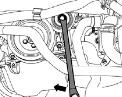
35.3 Loosening the belt tension
4. While pulling the tensioner, align the holes (see resist. illustration) and block the tensioner by inserting pin T10060A into these holes.
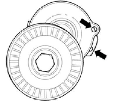
35.4 Fixing tensioner
5. If the belt being removed is to be reused, mark the direction of travel on the belt. Remove the accessory drive belt. If necessary, after removing the belt, you can remove / install its tensioner, as described in paragraphs 6-9. To install the belt, go to paragraph 10.
6. Remove the right pressure air hose (see resist. illustration) and casing together with radiator fans (see chapter 3).
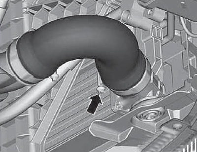
35.6 Right pressure air hose
7. Turn out bolts (arrows on resist. illustrations), release the coolant hose (3), loosen clamp (2), disconnect the connector (1) sensor ''G31" boost pressure with IAT sensor "G42" and remove the right pressure air tube.
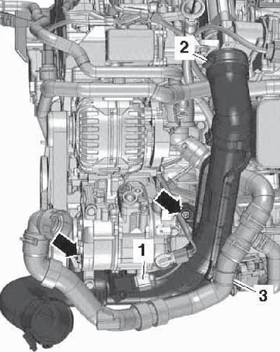
35.7 Removing the right pressure air tube
8. Remove the bolt (2 to resist. illustrations) and remove tensioner (1).
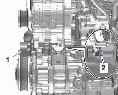
35.8 Removing the drive belt tensioner
9. The tensioner is installed in the reverse order. Use a new tensioner mounting bolt.
10. Before installing the belt, make sure that all accessories are securely fastened.
11. Lay the alternator belt first on the crankshaft pulley, and then on the compressor and alternator pulleys in accordance with the gasket diagram (see illustration 35.1). If a used belt is installed, the marks on it must face the direction of travel when the engine is running.
12. Slightly turn the belt tensioner in the direction of the arrow (see illustration 35.3) and remove lock pin T10060A to tighten the belt. Make sure the belt is properly seated on the pulleys.
Auxiliary bracket
13. For removal of an arm remove auxiliary units and turn out bolts of fastening of an arm.
14. Before installing the bracket, make sure that between it and the cylinder block in the threaded hole (6 on resist. illustrations) there is a bushing. Use new M10 bracket mounting bolts. bolts (1 and 2) have a length of 52 mm, bolts (3 and 4) - length 30 mm, and bolts (5 and 6) - length 60 mm. Tighten the bolts in sequence (1-6) first by hand, then with a force of 40 Nm, and then tighten the bolts (1 and 2) 90°, bolts (3 and 4) - at an angle of 45°, and the bolts (5 and 6) - at an angle of 90°.
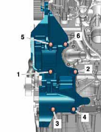
35.14 Bracket mounting bolts
Crankshaft pulley
15. Remove the accessory drive belt (see subsection above).
16. Remove the crankshaft pulley cover.
17. Loosen the pulley mounting bolts, holding it from turning with a spanner wrench on the central bolt (see resist. illustration). Remove the pulley.
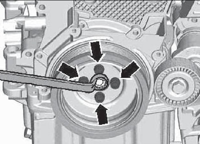
35.17 Removing the crankshaft pulley
18. Installation is carried out in the reverse order. The pulley is installed in only one position, because it has a centering hole. Use new pulley bolts.