



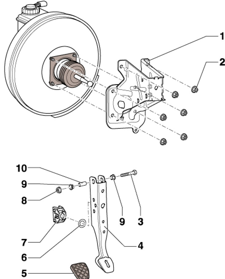
5.1. Brake pedal mounting parts 1. Brake pedal bracket; 2. Self-locking nut, subject to replacement, 25 Nm; 3. Bolt; 4. Brake pedal; 5. Overlay; 6. Bearing; 7. Support of the articulated head of the vacuum booster push rod; 8. Self-locking nut, 25 Nm; 9. Bushing; 10. Pedal axle
Separating and connecting the brake pedal from/to the vacuum booster
2. Remove the instrument panel trim on the driver's side. Press the brake pedal towards the brake booster and hold it.
3. Insert tool T10159A and pull it towards the driver's seat, holding the brake pedal so that it does not move backwards. Thus the holding paws (3 in the illustration) the supports are pressed away from the rod hinge (2).
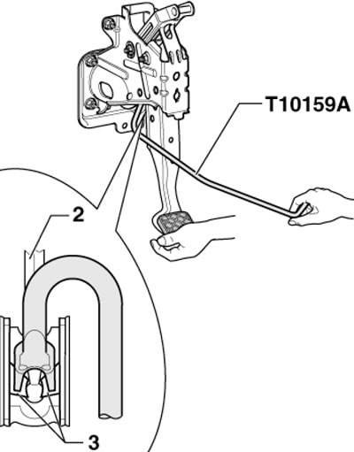
5.3. Separating the brake pedal from the vacuum booster
Note: For clarity, the pedal is shown removed.
4. Pull the T10159A tool together with the brake pedal towards the driver's seat - the pedal will separate from the vacuum booster rod hinge.
5. To connect the pedal to the booster, hold the plunger joint in front of the support and push the pedal towards the booster until it clicks into place (see illustration). Further connection is carried out in the reverse order.
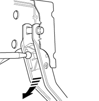
5.5. Connecting the brake pedal to the vacuum booster
Removal and installation of D/V "F" brake lights and sensor "F47" of the brake pedal position
Note: The brake light "F" and brake pedal position sensor "F47" are installed on the GHz (see illustration 6.1).
6. Remove the air cleaner (see Chapter 4).
7. Remove the battery and its holder (see Chapter 5).
8. Disconnect the connector (1 in the illustration) sensor assembly (3), unscrew the bolt (2) from the master cylinder and remove the sensor assembly from the locking tab (4).
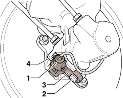
5.8. Removing the D/W brake lights
9. Installation is carried out in reverse order. Tighten the bolt to 5 Nm.