
Company vehicles Hyundai Company vehicles Kia Company vehicles Lada Company vehicles Mazda Company vehicles Mercedes-Benz Company vehicles Opel Company vehicles Mitsubishi
English Русский
Български
Беларускі
Український
Српски
Hrvatski
Română
Polski
Slovenský
Magyar
Articles   
Bookmark Contacts Sitemap
SkodaBook.ru


Fabia Rapid Octavia Superb Kodiaq Yeti Others
Yeti (2009-2017)

Removal and installation of the brake master cylinder, vacuum booster and brake fluid reservoir (Skoda Yeti 5L)

  • Main
  • Yeti
  • 5L (2009-2017)
  • Chassis (running gear)
  • Brake system
  • Removal and installation of the brake master cylinder, vacuum booster and brake fluid reservoir
0
Contents: Brake fluid reservoir and master…⬇ Removal and installation the vacuum…⬇
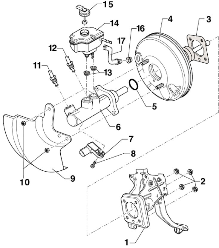
1. The parts of the brake master cylinder, brake booster and brake fluid reservoir are shown in the illustration.

6.1. Details of the brake booster unit, brake…

6.1. Details of the brake booster unit, brake booster and brake fluid reservoir 1. Brake pedal with bracket; 2, 10. Self-locking nut, subject to replacement, 25 Nm; 3. Vacuum booster gasket; 4. Brake booster; 5. Sealing ring; 6. Master brake cylinder, no repairs provided; 7. Assembly of D/V "F" brake lights and sensor "F47" of brake pedal position; 8. Bolt, 5 Nm; 9. Heat shield; 11. Brake line, from the secondary piston circuit of the CGT to the hydraulic modulator, 14 Nm; 12. Brake line, from the primary piston circuit of the GHZ to the hydraulic modulator, 14 Nm; 13. Compaction; 14. Brake fluid reservoir; 15. Cover, the connector should be in the recess; 16. Sealing the vacuum hose connection; 17. Vacuum hose, on AWD models - with vacuum sensor "G608"


Brake fluid reservoir and master cylinder


2. Remove the air cleaner (see Chapter 4).

3. Remove the battery together with its holder (see Chapter 5).


4. Place a lint-free cloth under the brake master cylinder to absorb brake fluid in the area where the engine and transmission meet.

5. Open the cap and pump out as much brake fluid as possible from the reservoir.

6. On models with manual transmission, disconnect the supply hose (In the illustration) clutch master cylinder, lift it up and tie it up so it doesn't get in the way. Alternatively, you can pinch the hose to prevent fluid from leaking out and then disconnect it from the reservoir.
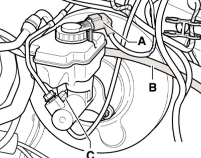
6.6 Brake fluid reservoir connections

6.6 Brake fluid reservoir connections


7. Disconnect the connector (And in illustration 6.6) low brake fluid level sensor and connector (C) D/W brake lights.

8. Remove the brake fluid reservoir by pressing its locking tabs outward and simultaneously pulling it out of the seals in the master cylinder.

9. Mark the brake pipes (1 in the illustration), disconnect them from the master cylinder and seal them. Loosen the nuts (2), remove the heat shield (if available) and carefully remove the master cylinder from the vacuum booster. If necessary, remove the sensor assembly from the master cylinder (see section 5).
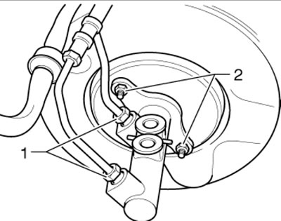


6.9. Connections and fasteners of the GTZ

6.9. Connections and fasteners of the GTZ


10. Installation is carried out in reverse order. When installing the brake master cylinder on the vacuum booster, make sure that the booster rod is correctly positioned in the brake master cylinder. Use new nuts to secure the brake master cylinder, tighten them with a force of 25 Nm. Tighten the nuts securing the brake lines to the brake master cylinder with a force of 14 Nm.

11. Finally, bleed the brake hydraulic drive and, on models with a manual transmission, the clutch hydraulic drive (see Chapter 1).

Removal and installation the vacuum booster


12. Remove the master cylinder (see subsection above).

13. Remove the vacuum hose from the vacuum booster.

14. Separate the brake pedal from the vacuum booster (see Section 5).

15. Give the nuts (1 in the illustration) and carefully remove the vacuum booster.
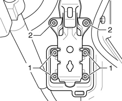
6.15. Fastening the vacuum booster

6.15. Fastening the vacuum booster


16. Installation is carried out in reverse order. Use new vacuum booster mounting nuts, tighten them to 25 Nm.

17. Finally, bleed the brake hydraulic drive and, on models with a manual transmission, the clutch hydraulic drive (see Chapter 1).
This article is available at russian, bulgarian, belarusian, ukrainian, serbian, croatian, romanian, polish, slovak, hungarian
Article verified: Timur Komissarov
Share with friends:
◀ Previous
Skoda Yeti: Brake system
Next ►

Removal and installation the brake pedal, D/W brake lights and brake pedal…
Repair and maintenance of the parking brake
Repair and maintenance of rear brake mechanisms
Repair and maintenance of front brake mechanisms
General information and safety precautions
Removal and installation the vacuum pump and sensor G608, checking the…
Removal and installation of the hydraulic modulator and ESP control unit
Read similar articles on other Skoda models

➧ Hydraulic control unit (ABS BOSCH 8.0), brake booster and brake… Skoda Fabia 2 (2007-2014)
➧ Checking the tightness of the master brake cylinder Skoda Rapid 1 (2012-2022)
➧ Vacuum brake booster, tandem master cylinder Skoda Octavia 1 (1996-2004)
➧ Removal and installation of the brake master cylinder, vacuum booster… Skoda Superb 2 (2008-2015)
➧ Checking the tightness of the master brake cylinder Skoda Kodiaq 1 (2016-2024)
➧ Removal, repair and installation of the master brake cylinder (MBC) Skoda Felicia (1994-2001)
Link to this article in various formats
Reviews and comments of visitors
No comments yet


Add two numbers: 21 + 30


Yeti (2009-2017) 
  • General information
  • Introduction to manual
  • Controls and instruments
  • Maintenance
  • Power unit
  • Petrol engine 1.2 l
  • Petrol engine 1.4 l
  • Petrol engine 1.8 l
  • Diesel engine 2.0 l
  • Cooling system
  • Power and control system
  • Exhaust system
  • Ignition and preheating systems
  • Starting and charging system
  • Transmission
  • Clutch
  • Manual gearbox
  • 7-speed gearbox DSG «0AM»
  • 6-speed gearbox DSG «02E»
  • Drive shafts
  • Chassis (running gear)
  • Brake system
  • Front suspension
  • Rear suspension
  • Steering
  • Body and interior
  • Heating and air conditioning
  • Exterior (external elements)
  • Interior (internal elements)
  • Electrical equipment
  • Equipment and devices
  • Lighting and signaling
  • Electrical diagrams
SkodaBook.ru © 2018–2026 | Mobile version | Articles on Skoda | Sitemap EN BG BY UA RS HR RO PL SK HU | Feedback | Site search | Bookmark
Fabia 1 (1999-2007) | Fabia 2 (2007-2014) | Rapid 1 (2012-2022) | Octavia 1 (1996-2004) | Octavia 3 (2013-2019) | Superb 2 (2008-2015) | Kodiaq 1 (2016-2024) | Yeti (2009-2017) | Favorit (1987-1994) | Felicia (1994-2001) |
By continuing to use the site, you agree to the use of cookies.