



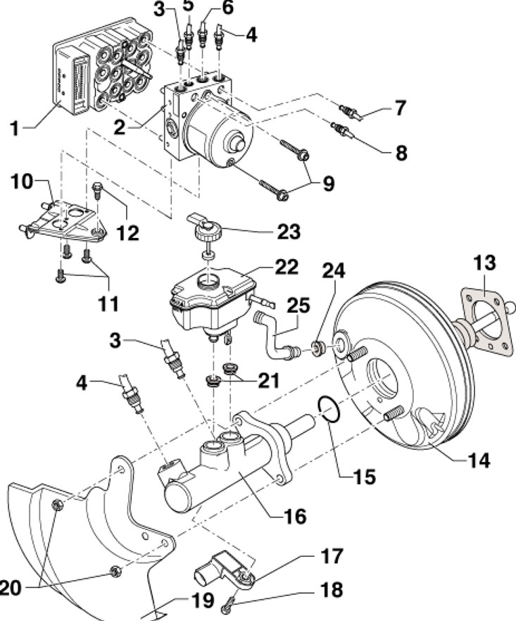
8.1. Installation details of the ESP control unit and hydraulic modulator 1. ESP control unit "J104", with built-in ESP sensor assembly "G419"; 2. Hydromodulator "N55" ESP; 3. Brake pipe, from the primary circuit of the master cylinder to the hydraulic modulator, diameter 6.5 mm, long nut M12x1; 4. Brake pipe, from the secondary circuit of the master cylinder to the hydraulic modulator, diameter 6.5 mm, long nut M12x1; 5. Brake pipe, to the front left caliper, diameter 5.25 Nm, union nut M10x1; 6. Brake pipe, to the front right caliper, diameter 5.25 Nm, union nut M12x1; 7. Brake pipe, to the rear left caliper, diameter 5.25 Nm, union nut M12x1; 8. Brake pipe, to the rear right caliper, diameter 5.25 Nm, union nut M10x1; 9. Bolt, 5.5 Nm; 10. Bracket; 11, 12. Bolts, 8 Nm; 13. Vacuum booster gasket; 14. Vacuum booster; 15. Vacuum booster sealing ring; 16. GTZ; 17. Assembly of D/V "F" brake lights and sensor "F47" of brake pedal position; 18. Bolt, 5 Nm; 19. Heat shield; 20. Nut, subject to replacement, 25 Nm; 21. Seals; 22. Brake fluid reservoir; 23. Tank cover 22; 24. Sealing the hose 25; 25. Vacuum hose
2. Using a diagnostic tool, read and write down the existing control unit code.
3. Disconnect the negative cable from the battery.
4. Remove the top engine cover (if available).
5. On 1.8L engines, remove the upper boost air hose.
6. On diesel engines, remove the exhaust gas pressure sensor No. 1 "G450", disconnect the connectors, unscrew the diesel particulate filter and put it aside.
The original can be viewed on: SKODABOOK
7. On models with a diesel particulate filter, remove the diesel particulate filter (see chapter 4).
8. Remove the connector lock in the direction of the arrow (1 in the illustration) and disconnect the connector in the direction of the arrow (2).
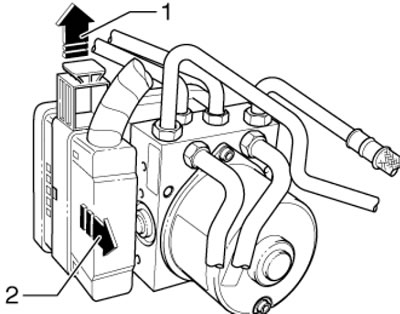
8.8. Disconnecting the connector
9. Fix the depressed brake pedal with the VAG1869/2 tool or ask an assistant to depress and hold the brake pedal.
10. Connect the hoses to the bleed nipples of the front left and rear left calipers; place the other ends of the hoses in a container to collect the brake fluid. Open the nipples and, using an assistant or the VAG1869/2 device, press the brake pedal at least 60 mm. Close the nipples. Do not release the brake pedal.
11. Place a lint-free cloth under the ESP control unit and hydraulic modulator assembly to absorb the brake fluid.
12. Mark the brake pipes coming from the brake master cylinder, disconnect them from the hydraulic modulator and plug the pipes and holes in the hydraulic modulator.
13. Mark the brake pipes going to the calipers, disconnect them from the hydraulic modulator and plug the pipes and holes in the hydraulic modulator.
14. Pull the control unit and hydraulic modulator assembly out of the rubber dampers in an upward direction.
15. Installation is carried out in reverse order. Tighten the assembly mounting bolts on the bracket with a force of 8 Nm. Tighten the brake line nuts on the hydraulic modulator with a force of 14 Nm.
16. Finally, bleed the brake hydraulic system (see Chapter 1) and code the ESP unit "J104" using a diagnostic tool. To do this, apply the basic settings for the steering angle sensor "G85", the lateral acceleration sensor "G200" and the brake pressure sensor "G201".