



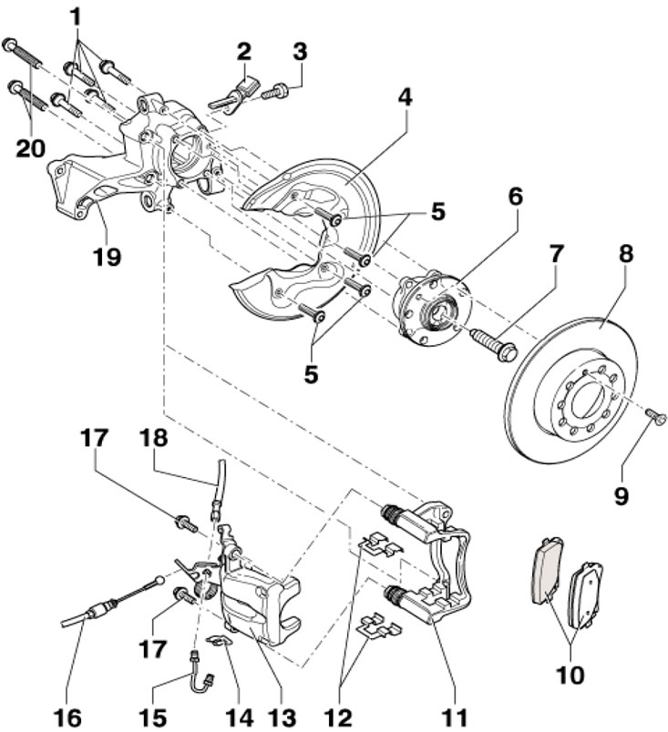
3.1a. Rear brake mechanism parts CII-41 (aWD models) 1, 7. Bolt, subject to replacement, 70 Nm, then tighten to an angle of 90°; 2. ABS sensor, before installation, clean the walls of the mounting hole and apply grease G 052 112 AZ to them; 3. Bolt, 8 Nm; 4. Brake shield, different options available; 5. Bolt, 12 Nm; 6. Hub assembly, with built-in sensor rotor 2; 8. Brake disc, replaced on both sides at the same time; 9. Bolt, 4 Nm; 10. Brake pads; 11. Anchor bracket, with guide pins and caps; 12. Brake pad holders, subject to replacement when replacing the pads; 13. Support; 14. Tube retainer 15; 15. Brake pipe, 14 Nm; 16. Parking brake cable; 17. Self-locking bolt, subject to replacement, 35 Nm; 18. Brake hose; 19. Hub assembly holder; 20. Bolt, subject to replacement, 90 Nm, then tighten to an angle of 90°
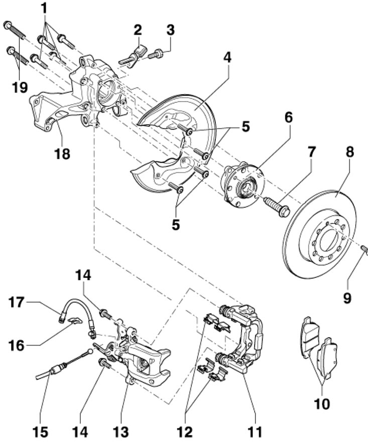
3.1b. Bosch BIRIII rear brake parts (aWD models) 1-13. See captions to illustration 3.1a; 14. Self-locking bolt, subject to replacement, 35 Nm; 15. Parking brake cable; 16. Hose retainer 17; 17. Brake hose, with union nut and hollow bolt, 35 Nm; 18. Hub assembly holder; 19. Bolt, subject to replacement, 90 Nm, then tighten to an angle of 90°
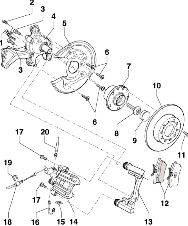
3.1c. CI-38 Rear Brake Parts (fWD models) 1. ABS sensor, before installation, clean the walls of the mounting hole and apply grease G 052 112 AZ to them; 2. Bolt, 8 Nm; 3. Bolt, subject to replacement, 90 Nm, then tighten to an angle of 90°; 4. Hub assembly holder; 5. Brake mechanism shield; 6. Bolt, 12 Nm; 7. Hub assembly, with built-in sensor rotor 1; 8. Hub bolt, must be replaced, 180 Nm, then tighten to an angle of 180°; 9. Bolt cap 8; 10. Brake disc, replaced on both sides at the same time; 11. Bolt, 4 Nm; 12. Brake pads; 13. Anchor bracket, with guide pins and caps; 14. Support; 15. Tube retainer 16; 16. Brake pipe, 14 Nm; 17. Self-locking bolt, subject to replacement, 35 Nm; 18. Parking brake cable; 19. Spring lock for cable 18, on some models; 20. Brake hose
Replacing the pads
Note: Brake pads should be replaced in pairs and on both wheels of the same axle at the same time.
Note: If the pads are not being removed for replacement, i.e. will be reinstalled, mark them before removal so that they can be reinstalled in their original locations.
2. Jack up the car and place it on supports. Remove the rear wheel.
3. Remove the caliper mounting bolts while holding the guide pins with an open-end wrench (see illustration). Remove the caliper from the anchor bracket without disconnecting the brake hose from it, and secure the caliper to the wire, preventing tension on the hose.
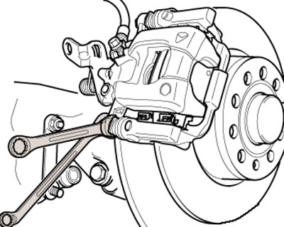
3.3. Unscrewing the caliper mounting bolts (on the example of Bosch BIRIII)
4. Remove the brake pads and, on CII-41 and Bosch BIRIII mechanisms, their holders (see illustration).
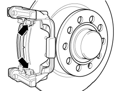
3.4. Brake pad holders (on the example of Bosch BIRIII)
5. Before installing the pads, press the piston into the brake wheel cylinder using a suitable tool (see illustration). Do not damage the piston dust boot. At the same time, make sure that the brake fluid does not spill out of the reservoir; pump it out if necessary.
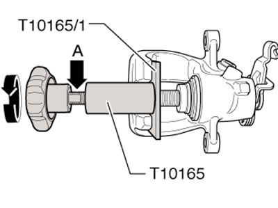
3.5. Pressing in the piston
6. Thoroughly clean the caliper and mating surfaces of the pads. If there is a protective coating on the new pads, remove it. Use only methylated spirits for cleaning, do not blow out brake pad dust with compressed air.
7. Install the pads (if available - with holders) in the support. If new pads are installed, use new retainers (except for CI-38 mechanisms). Make sure the pads are positioned correctly in the holders (except for CI-38 mechanisms).
8. Install the caliper and secure it to the anchor bracket by tightening the new self-locking bolts to 35 Nm. Keep the guide pins from turning while doing this.
Note: New self-locking bolts (4 pcs.) are included in the repair kit.
9. Install the wheels and, with the vehicle stationary, press the brake pedal hard several times until the pads reach their working position.
10. Correct the brake fluid level.
Removal and installation, repair of the caliper
11. Jack up the car and place it on supports. Remove the rear wheel.
12. Disconnect the parking brake cable from the lever on the caliper, then remove the spring clip and pull the cable out of the holder on the caliper.
13. Connect a hose to the bleed nipple on the caliper, and lower the other end of this hose into a container to collect the brake fluid. Open the bleed nipple, press the brake pedal with the VAG1869/2 tool (or ask an assistant), close the bleed nipple and disconnect the hose.
14. Disconnect the brake caliper line.
15. Remove the caliper mounting bolts while holding the guide pins with an open-end wrench (see illustration 3.3).
16. Remove the caliper from the anchor bracket. If you need to repair the caliper (piston replacement) be guided by the support. illustrations.
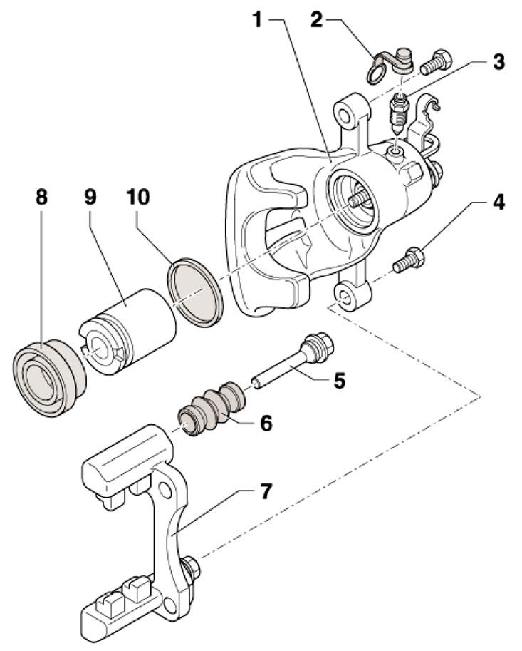
3.16a. CI-38 rear brake caliper parts (fWD models); cII-41 brake mechanisms (aWD models) - similarly 1. Caliper, with parking brake lever; if the lever is not sealed, after replacement, pre-bleed the caliper; 2. Cap; 3. Bleed nipple, 10 Nm, lightly lubricate the thread with sealant G 052 150 A2 before installation; 4. Self-locking bolt, subject to replacement, 35 Nm; 5. Guide pin, lubricate before installation; 6. Dust cover, pulled over bracket 7 and finger 5; 7. Anchor bracket with guide pins and their dust boots; 8. The dust cover is pulled by the outer sealing lip onto the piston; 9. Piston with automatic regulator, before installation apply a thin layer of grease G 052 150 A2; 10. Cuff
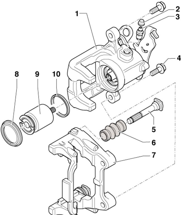
3.16b. Bosch BIRIII rear brake caliper parts (aWD models)
17. Follow the steps described in paragraphs 5-7.
18. Connect the brake line to the caliper and bleed the brake hydraulic system.
19. Connect and adjust the parking brake cable (see Section 4).
20. Follow the steps described in paragraphs 9-10.