



Contents: Work with the front suspension…⬇ Fixing the position of the subframe…⬇ Removal and installation the subframe ⬇
Work with the front suspension subframe
1. Subframe installation details are shown on illustrations 1.1a-b. The following steps are described for models with an aluminum subframe.
Fixing the position of the subframe and consoles
2. Screw the T10096 centering pins into the places one by one (1-4 in the illustration) with a force of no more than 20 Nm.
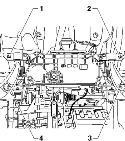
3.2. Places for screwing centering pins into the subframe
Note: If the specified force is exceeded, the pin threads may be damaged.
3. Replace the support bracket bolts on both sides with T10096 centering pins one by one (see illustration), tightening them to 20 Nm.
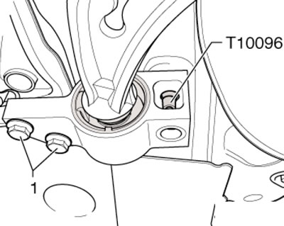
3.3. Places for screwing the centering pins into the bracket
4. Replace the console mounting bolts with T10096 centering pins one by one (see illustration), tightening them to 20 Nm.
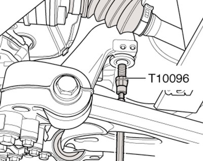
3.4. Screwing in the centering pin instead of the console bolt
5. As a result of the actions described in paragraphs 2-4, the position of the front subframe is fixed. After this, you can remove the anti-roll bar and steering gear.
6. Replacing the centering pins with standard bolts is done in the reverse order. Use new bolts.
Removal and installation the subframe
Note: The subframe is removed together with the suspension arms.
7. Remove the sound insulation under the engine compartment (see Chapter 11).
8. Remove the front wheels.
9. If equipped, disconnect the front suspension height sensor rod from the left suspension arm (see Section 8).
10. Loosen the nuts on both sides of the car (see illustration 4.5 Chapter 8) and separate the ball joint from the front suspension arm. Remove the exhaust system bracket from the subframe.
11. Remove the bolts (14 in the illustration) and separate the rocker support from the transmission. Secure the subframe as described in the subsection above. Remove the bolts (3 and 6) securing the steering gear and tie it with wire so that it does not change position. Then unscrew the bolts (11 and 16) of the stabilizer and also tie it up.
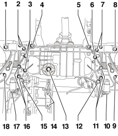
3.11. Subframe mounting bolts
12. Install the VAG1383A transmission jack under the subframe, placing a wooden block between them (1 in the illustration).
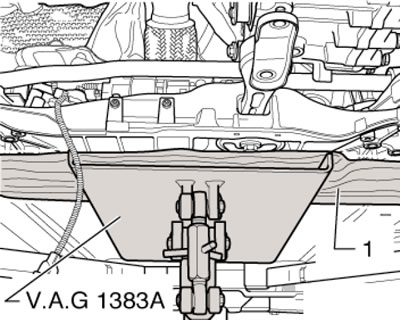
3.12. Securing the subframe on the jack
13. If there is a front suspension height sensor, disconnect its connector (see Section 8).
14. Remove the bolts (4 and 5 in illustration 3.11) and carefully lower the subframe with consoles on the jack, paying attention to the electrical wiring. If necessary, disconnect the electrical wiring connectors.
15. Installation is carried out in reverse order.