



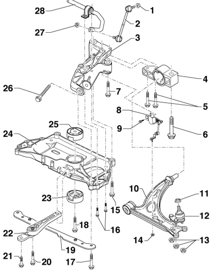
1.1a. Fastening parts of the front subframe, stabilizer and front suspension arm (models with aluminum subframe) 1, 27. Self-locking nut, subject to replacement, 65 Nm, when tightening, hold by the hinge polygon; 2. Stabilizer bar 28, between the stabilizer and the suspension bar; 3. The console must be replaced when adjusting the front wheel alignment angles; 4. Bracket with glued rubber bushing; 5. Bolt M10x76, subject to replacement, 50 Nm, then tighten to an angle of 90°; 6, 7. Bolt M12x1.5x90, subject to replacement, 70 Nm, then tighten to an angle of 180°; 8. Front left "G78" suspension height sensor, on models with automatic headlight leveling since 11.2009.; 9. Bolt, 9 Nm, only on models from 11.2009.; 10. Suspension arm, arms made of the same material must be installed on both sides, if damaged, the ball joint must be replaced along with the arm; 11. Self-locking nut, subject to replacement, 60 Nm; 12. Ball joint, if damaged, the lever must be replaced together with the support; 13. Self-locking nut, subject to replacement, 60 Nm; 14. Nut, 9 Nm, only on models from 11.2009.; 15. Bolt M12x1.5x100, subject to replacement, 70 Nm, then tighten to an angle of 90°; 16. Bolt M8x75, subject to replacement, 20 Nm, then tighten to an angle of 90°; 17. Bolt M12x1.5x75, subject to replacement, 70 Nm, then tighten to an angle of 90°; 18. Bolt M14x1.5x70, to be replaced, 100 Nm, then tighten to an angle of 90°, first tighten when the rocker support is bolted to the transmission; 19. Soundproofing holder; 20. Bolt M 10x75, subject to replacement; 21. Bolt M10x35, subject to replacement; 22. Swing support, first fix to the transmission, then to the subframe; 23. Lower rubber-metal bushing of the rocking support; 24. Subframe; 25. Upper rubber-metal bushing of the rocking support; 26. Bolt M12x1.5x110, subject to replacement, 70 Nm, then tighten to an angle of 180°, tightened with the suspension unloaded; 28. Anti-roll bar
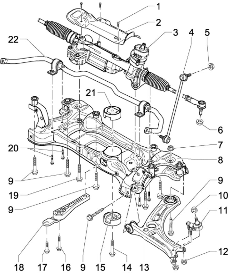
1.1b. Front subframe, stabilizer and front suspension arm mounting parts (models with steel subframe) 1. Bolt, 6 Nm; 2. Heat shield; 3. Steering mechanism; 4. Stabilizer bar 22, between the stabilizer and the suspension bar; 5. Nut, 65 Nm; 6. Nut, subject to replacement, 20 Nm, then tighten to an angle of 90°; 7. Nut, to be replaced, 70 Nm, then tighten to an angle of 180°, hold while tightening the bolt 9; 8. Subframe, welded part is made of steel; 9. Bolt, subject to replacement, 70 Nm, then tighten to an angle of 180°, while tightening hold the nut 7; 10. Self-locking nut, subject to replacement, 60 Nm; 11. Ball joint, if damaged, replace the lever together with the support; 12. Self-locking nut, subject to replacement, 100 Nm; 13. Suspension arm, arms made of the same material must be installed on both sides, if damaged, the ball joint must be replaced along with the arm; 14. Bolt M14x1.5x70, subject to replacement, 100 Nm, then tighten to an angle of 90°, first tighten when the rocker support is bolted to the transmission; 15. Lower rubber-metal bushing of the rocking support; 16. Bolt M10x75, subject to replacement; 17. Bolt M10x35, subject to replacement; 18. Swinging support; 19. Bolt M10x76, subject to replacement, 50 Nm, then tighten to an angle of 90°; 20. Bolt M8x75, subject to replacement, 20 Nm, then tighten to an angle of 90°; 21. Upper rubber-metal bushing of the rocking support; 22. Anti-roll bar
Rear suspension - independent, multi-link, with separately mounted shock absorbers and springs (see illustrations 1.2ad and 1.3a-b) The hub assembly holder assembly is shown in illustrations 3.1a-b Chapters 8.

1.2a. Subframe and rear suspension arms of FWD models up to week 21 of 2010. Arrow Direction of movement; 1. Eccentric bolt for camber adjustment, do not turn more than 90° in each direction; 2, 5. Self-locking nut, subject to replacement, 95 Nm, tightened with unloaded suspension; 3, 6. Eccentric washer, inner hole with protrusion; 4. Toe-in adjustment eccentric bolt, do not turn more than 90° in each direction; 7. Subframe; 8. Bolt, subject to replacement, 90 Nm, then tighten to an angle of 90°; 9. Lower wishbone; 10. Self-locking nut, subject to replacement, 90 Nm, then tighten to an angle of 90°, tightened with the suspension unloaded; 11. Bolt, subject to replacement; 12. Threaded bushings M6; 13. Spacer sleeve; 14. Protection from stones; 15. Bolt, 8 Nm; 16. Self-locking nut, subject to replacement, 130 Nm, then tighten to an angle of 90°, tightened with the suspension unloaded; 17. Bolt, subject to replacement, 130 Nm, then tighten to an angle of 90°, tightened with the suspension unloaded; 18, 20. Washer; 19. Upper wishbone; 21. Self-locking nut, subject to replacement, tightened with the suspension unloaded by turning bolt 17; 22. ABS sensor wiring holder, fixed to lever 19; 23. Hub assembly holder; 24, 27. Washer; 25. Bolt, subject to replacement, tightened with unloaded suspension; 26. Guide lever; 28. Self-locking nut, subject to replacement, 90 Nm, then tighten to an angle of 90°, tightened with the suspension unloaded; 29. Bolt, subject to replacement, tightened with unloaded suspension
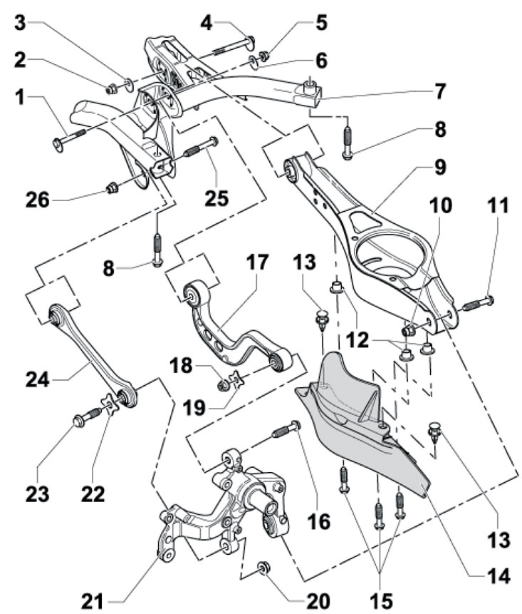
1.2b. Subframe and rear suspension arms FWD models from week 22 2010. 1. Eccentric bolt for camber adjustment, do not turn more than 90° in each direction; 2, 5. Self-locking nut, subject to replacement, 95 Nm, tightened with unloaded suspension; 3, 6. Eccentric washer, inner hole with protrusion; 4. Toe-in adjustment eccentric bolt, do not turn more than 90° in each direction; 7. Subframe; 8. Bolt, subject to replacement, 90 Nm, then tighten to an angle of 90°; 9. Lower wishbone; 10. Self-locking nut, subject to replacement, 90 Nm, then tighten to an angle of 90°, tightened with the suspension unloaded; 11. Bolt, subject to replacement; 12. Threaded bushings MB; 13. Spacer sleeve; 14. Protection from stones; 15. Bolt, 8 Nm; 16. Bolt, subject to replacement, 130 Nm, then tighten to an angle of 90°, tightened with the suspension unloaded; 17. Upper wishbone; 18. Self-locking nut, subject to replacement, tightened by turning bolt 16; 19, 22. Washer; 20. Self-locking nut, subject to replacement, is tightened with the suspension unloaded by turning bolt 23; 21. Hub assembly holder; 23. Bolt, subject to replacement, 130 Nm, then tighten to an angle of 90°, tightened with the suspension unloaded; 24. Guide lever; 25. Bolt, subject to replacement; 26. Self-locking nut, subject to replacement, 90 Nm, then tighten to an angle of 90°, tightened with the suspension unloaded
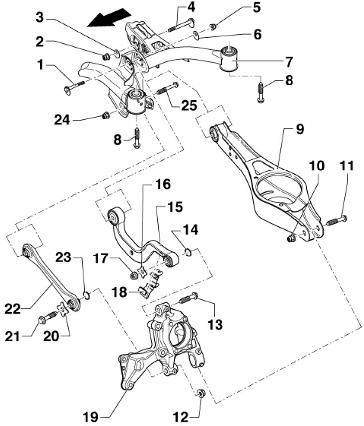
1.2c. Subframe and rear suspension arms of AWD models Arrow Direction of movement; 1. Eccentric bolt for camber adjustment, do not turn more than 90° in each direction; 2, 5. Self-locking nut, subject to replacement, 95 Nm, tightened with unloaded suspension; 3, 6. Eccentric washer, inner hole with protrusion; 4. Toe-in adjustment eccentric bolt, do not turn more than 90° in each direction; 7. Subframe; 8. Bolt, subject to replacement, 90 Nm, then tighten to an angle of 90°; 9. Lower wishbone; 10. Self-locking nut, subject to replacement, 90 Nm, then tighten to an angle of 90°, tightened with the suspension unloaded by turning bolt 11; 11. Bolt, subject to replacement; 12. Self-locking nut, subject to replacement, 130 Nm, then tighten to an angle of 90°, tightened with the suspension unloaded; 13. Bolt, subject to replacement, 130 Nm, then tighten to an angle of 90°, tightened with the suspension unloaded; 14, 16. Washer; 15. Upper wishbone; 17. Self-locking nut, subject to replacement, 130 Nm, then tighten to an angle of 90°, tightened with the suspension unloaded by turning bolt 13; 18. ABS sensor wiring holder, fixed to lever 15; 19. Hub assembly holder; 20, 23. Washer; 21. Bolt, subject to replacement, tightened with unloaded suspension; 22. Guide lever; 23. Self-locking nut, to be replaced, 90 Nm, then tighten to an angle of 90°; 24. Bolt, subject to replacement, tightened with unloaded suspension
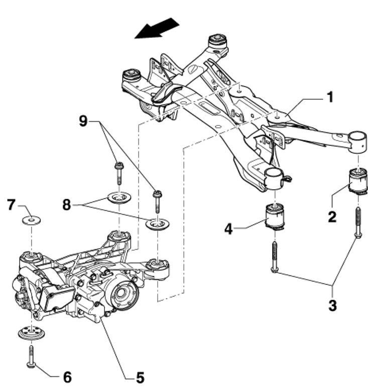
1.2d. Subframe and final drive of FWD models Arrow Direction of movement 1. Subframe; 2/4. Rear/front glued rubber bushing; 3. Bolt, subject to replacement, 90 Nm, then tighten to an angle of 90°; 5. Rear final drive; 6, 9. Bolt, subject to replacement, 60 Nm, then tighten to an angle of 90°; 7, 8. Washer
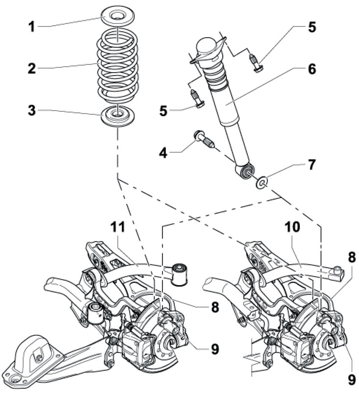
1.For. Spring and shock absorber of rear suspension of FWD models 1. Upper spring seat; 2. Spring; 3. Lower spring seat; 4. Bolt: on AWD models - 180 Nm; on FWD models - tighten with unloaded suspension (130 Nm, then tighten to 90° angle); 5. Bolt, subject to replacement, 50 Nm then tighten to an angle of 45°; 6. Shock absorber; 7. Washer; 8. Lower wishbone; 9. Hub assembly holder
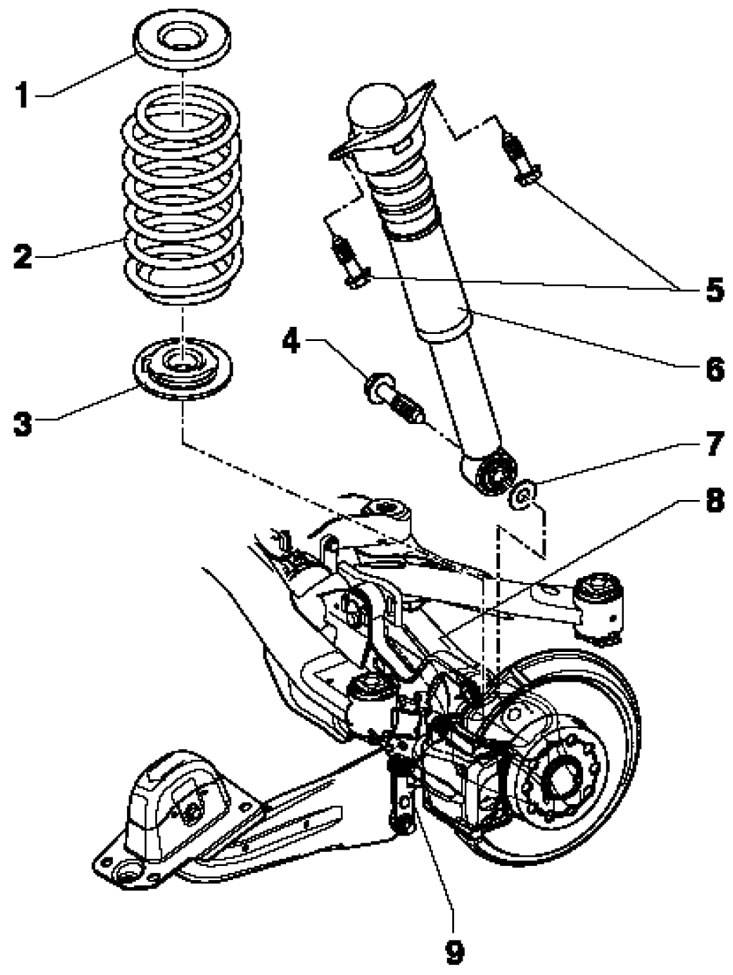
1.3b. Spring and shock absorber of rear suspension of AWD models See captions for illustration 1.3a
The suspension modification can be identified by the PR number on the vehicle data sticker (see illustration 1.4), located on the floor of the luggage compartment and in the service book (see Introduction).
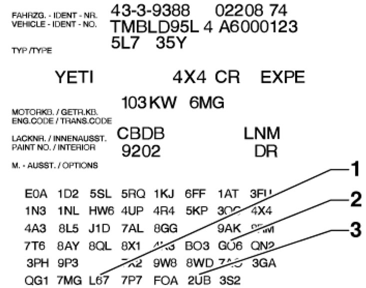
1.4. Identification of suspension 1. Springs; 2. Shock absorbers; 3. Chassis
The steering system consists of a steering wheel, a steering shaft, a rack and pinion steering mechanism and a steering gear. The steering wheel with built-in front driver airbag is mounted on a shaft that transmits steering movements to the steering gear. The steering column switch assembly is installed behind the steering wheel. To maintain contact between the airbag and the SRS control unit when the steering wheel is turned, a coil spring is used that can twist and untwist. The coil spring consists of a tape with internal conductive tracks. The steering column can be adjusted for both reach and tilt.
To make driving easier, the car is equipped with a 3rd generation electromechanical power steering with two leading gears. A separate transmission is added to the simple steering mechanism, acting on the steering rack and driven by an electric motor. The torque sensor on the steering shaft, acting on the steering wheel with the steering angle sensor, is located in the steering gearbox. Communication is carried out via the CAN data bus. The advantages of this design include:
- low energy consumption (the booster only uses energy when it is actually working, when the steering wheel is turned);
- hydraulic components fall off (pump, lines and power steering reservoir);
- minimal transmission of impacts to the steering wheel (for example, when driving on an uneven road);
- low noise transmission to the vehicle;
- the "active return" function helps return the wheels to a straight position
When performing repairs or servicing of suspension and steering components, problems often arise with loosening "stuck" bolts and nuts. The fastening elements located under the bottom of the car are constantly exposed to external influences and over time they corrode and partially deteriorate. Using brute force to loosen such a "stuck" fastener carries the risk of damaging it. First, wet the non-removable element with a small amount of special penetrating liquid (for example, WD-40), allowing it to soak into the rust layer well. Use a wire brush to remove external deposits from accessible areas of threaded surfaces. Sometimes a sharp blow with a hammer on the nut through a drift helps to destroy the rust filling the gaps between the threads of the threaded joint - try not to damage the threads as a result of the drift coming off. Using a long handle when loosening a "stuck" fastener allows you to significantly increase the applied torque, but it should be remembered that using extensions in a set with ratchet-type drives is associated with the risk of failure of the return mechanism, as well as the possibility of injury. Self-locking nuts and fasteners damaged by corrosion or removal during repairs must be replaced without fail. Welding and straightening are not permitted on bearings that carry loads and on suspension components that guide the wheel.
Since most of the procedures described in this chapter are performed on a vehicle raised above the ground, you should take care in advance of options for securely fixing it in a raised position - prepare strong supports. To jack up the vehicle, use a hydraulic rolling jack - remember that the standard onboard jack is only intended for temporary jacking of the vehicle when replacing a broken wheel. A hydraulic jack can also be used to lift some suspension components while performing a particular procedure. Before carrying out any work, secure the vehicle to the lift legs using safety belts.
Attention: It is not permitted to carry out work under a vehicle that is held in a raised position only by means of jacks!