



Note: Only the toe-in of the front and rear wheels can be adjusted.
1. The geometry of the suspension and its rigidity determine the possibility of limiting the vertical movements of the body and reducing angular vibrations around the transverse and longitudinal axes.
2. The front wheels rotate around inclined axles, whose position is determined by the hinges and suspension parts of the car.
3. The most important are the following kinematic settings of wheel assemblies in relation to steering and the transmission of forces between the tires and the road surface. Wheel alignment has a significant impact on vehicle stability, tire wear and fuel consumption. The nominal values of the wheel alignment angles to be checked and adjusted for the vehicles covered in this Manual are given in the Specifications at the beginning of the chapter.
4. Convergence (convergence) is the angle between the lines formed by the intersection of the horizontal plane of the planes of the wheel assemblies of one axle of the vehicle; toe-in can also be defined as the difference in distances between the front and rear flanges of the wheel rims (see illustration). Toe-in affects the straightness of the vehicle's movement and its controllability, and on front-wheel drive models it compensates for the resulting kinematic changes in the suspension geometry determined by the effect of traction force. At zero toe-in, the distance between the front edges of the wheels is equal to the distance between their rear edges.
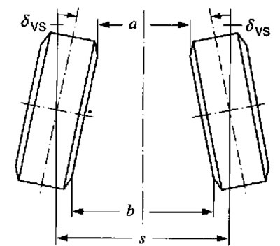
18.4. Front wheel toe-in δvs. Wheel alignment angle; α. Distance between the front edges of the wheels; b. Distance between rear edges of wheels; s. Track; b-a. Convergence
5. Collapse (see illustration) is called the angle between the lines formed by the intersection of the following three planes:
- a vertical plane drawn through the centers of the wheel assemblies of one axle of a vehicle;
- plane of symmetry of the car;
- wheel disk plane.
If the top of the wheel is tilted towards the car's axis of symmetry, the camber is called negative, and vice versa. Correct camber adjustment determines the size and position of the contact patch of the treads with the road surface and allows compensation for changes in the suspension geometry that occur during turns and when the car is moving on an uneven road surface.
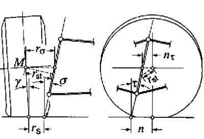
18.5. Wheel alignment angles M - Wheel Assembly Center; rst - Kinematic length of the journal; nτ - Longitudinal displacement of the wheel pivot axis; n - Positive stabilization arm; t - Angle of longitudinal inclination of the wheel turning axis; rδ - Lateral displacement of the wheel pivot axis; rs - Rolling shoulder S; γ - Camber angle; δ - Angle of transverse inclination of the wheel pivot axis
6. The kinematic length of the journal is the shortest distance between the center of the steering wheel and its axis of rotation (see illustration 18.5).
7. The stabilization shoulder is the distance between the point of contact of the wheel and the point of intersection of its rotation axis with the road surface in the side view (see illustration 18.5), determining the magnitude of the stabilizing moment and influencing the directional stability of the vehicle and the distribution of forces in the steering when making turns.
8. Wheel yaw angle - the angle between the yaw axis and the vertical in the side view (see illustration 18.5). Together with the lateral tilt angle of the axle (see below), the coasting affects the change in wheel camber when measuring the steering wheel angle, as well as the stabilizing moment.
9. The rolling shoulder is defined as the distance between the point of contact of the wheel with the road surface and the point of intersection of its turning axis with the road surface in the front view (see illustration 18.5). The leverage is considered negative when the last of the above points is between the center and the outside of the wheel. The parameter influences the degree of impact of braking forces on the steering wheel and the magnitude of the stabilizing moment, and a negative running-in arm increases the latter.
10. The angle of the transverse inclination of the wheel rotation axis is the angle between the wheel rotation axis and the vertical in the plane of the vehicle's cross section (see illustration 18.5). Along with the coasting (see above) and the magnitude of the longitudinal displacement of the pivot axis (see ibid) affects the sensitivity of the steering.
Conditions for checking wheel alignment angles
11. Checking the wheel alignment angles of a vehicle requires a specially equipped lift. Before starting the check, make sure that the following conditions are met:
- fuel, coolant and lubricants are full (if the tank is not full, compensate for the lack of weight by placing an appropriate weight on the central rear seat, based on the fact that half a tank corresponds to 24 kg);
- there should be no people or luggage in the passenger compartment or luggage compartment;
- the on-board tool kit and spare wheel are in their place;
- the air pressure in the tires corresponds to the nominal;
- the tread depth of the tires mounted on the wheels of the same axle is the same and is not less than 2 mm;
- the runout and play of the wheel rims, hub assemblies, ball joints of the front suspension and steering rod ends are normal;
- the front wheels are set to the straight-ahead position;
- the steering column is set to the middle height adjustment position;
- the car is leveled, i.e. the suspension is rocked several times.
12. When adjusting, it is necessary to check both axles, otherwise the steering rack may be offset from the center. It is not recommended to check the wheel alignment angles when testing up to 2000 km, since the suspension springs may not have settled yet.
13. Only the camber and toe-in of the wheels are subject to adjustment. The front wheel run-out is not adjustable, but should be checked to determine the condition of the suspension.
14. It is necessary to check the wheel alignment angles in the following cases:
- the car "doesn't hold the road";
- the car was involved in an accident;
- there is uneven wear on the wheel tread;
- the following were removed/installed: steering gear, steering rod or its end, any rear suspension arms, as well as (if the subframe was not secured during removal): Front suspension arm, front aluminum subframe console, front steel subframe and front stabilizer;
- the following have been replaced: steering gear, tie rod or tie rod end, steering knuckle, aluminum subframe console, steel subframe, any rear suspension arms, rear suspension subframe or rear hub assembly carrier, and (if the subframe was not secured during removal): front suspension arm rubber bushing and front stabilizer.
15. Checking/adjusting the wheel alignment angles is performed in the following order: (you should move on to the next point only after completing the current point):
- front wheel alignment;
- rear wheel alignment;
- rear wheel alignment;
- front wheel runout;
- front wheel alignment.