



Note: The description of the removal/installation of the steering column switches is given in Section 9, and the spiral spring - in Section 14; the steering column electronics control unit of models from 06.2010 is combined with a coil spring.
1. The location of the electrical components of the steering column is shown in the illustrations. The following describes the removal/installation of steering column components only for models up to 05.2010.
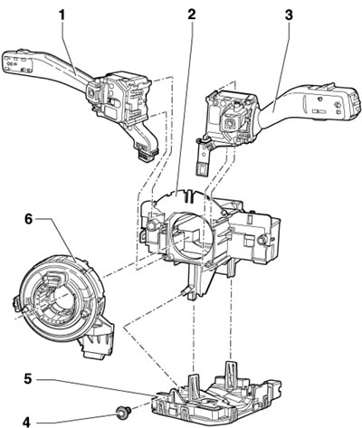
17.1a. Location of electrical components of the steering column before 05.2010. 1. Left steering column switch; 2. Steering column switch support; 3. Right steering column switch; 4. Screw, 0.4 Nm; 5. Steering column electronics control unit "J527"; 6. Spiral spring "F350"
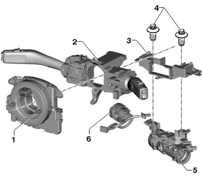
17.1b. Steering column electrical components layout as of 06.2010. 1. Coil spring "F350" with block "J527" of control of electronics of steering column; 2. Assembly of steering column switches; 3. Assembly support 2; 4. Shear bolts, approx. 15 Nm; 5. Steering column lock housing; 6. Ignition switch
Steering Column Electronics Control Unit
2. Remove the steering wheel and steering column trim covers (see Chapter 10).
3. Remove the screw (1 in the illustration), insert a 2.5 mm drill bit (2) into the hole (arrow 1) and release the latch in the direction of the arrow (2).
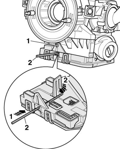
17.3. Releasing the far latch
4. Press the latch on the connector side in the direction of the arrow (see illustration), to unhook it, and then carefully remove the control unit from the switches straight down, without tilting it.
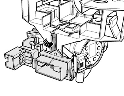
17.4 Releasing the front latch
5. Disconnect the connector (1 in the illustration), pull the lock (3) out of the connector (2), press the latch (arrow B) and disconnect the connector.
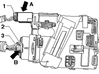
17.5. Wiring connectors of the "J527" unit
6. Installation is carried out in reverse order. After installing a new unit, it must be programmed.
Steering column switch support
Note: During the work, you will have to drill out the bolts that secure the steering column lock, so you should first remove the adjacent parts so that no metal particles from the bolts get on them.
7. Remove the steering column electronics control unit (see subsection above).
8. Remove the coil spring (see Section 14).
9. Remove both steering column switches (see Section 9).
Material published on the website (SkodaBook.ru)
10. Disconnect the immobilizer reading coil connector (arrow on the illustration), drill out the bolts (1) of the steering column lock with the cylinder and ignition switch (3) and slide the support (2) together with the steering column lock off the steering column.
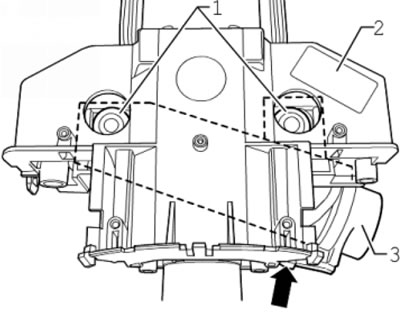
17.10. Steering column lock bolts (1)
11. Press the clamps (arrows in the illustration) and remove the steering column lock housing (2) from the support (1).
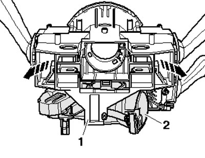
11/17 Removing the steering column switch support
12. Installation is carried out in reverse order. Use new shear head bolts.