



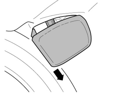
12.1a. Removing the front injector
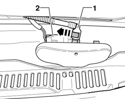
12.1b. Front injector connections
Text taken from this website (SkodaBook)
2. To remove the rear window washer fluid nozzle, open its cover and pull out the nozzle with pliers (see illustration).
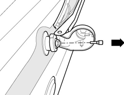
12.2. Removing the rear injector
Washer fluid reservoir, pumps and low washer fluid level sensor
Note: Depending on the version, the position of individual components and hose connections may differ from that shown in the illustrations. On models with an additional heater, the sensors and pumps are located differently, but the procedures for removing them are identical to those described.
3. Turn off the ignition.
4. Remove the front bumper cover (see chapter 11).
5. Disconnect the connectors (2 and 10 in the illustration) pump wiring (4 and 9), as well as the connector (6) of the sensor (7). Pull out the connection clamps (5 and 3) and separate the connections from the pump (4), collecting the leaking liquid. Press the lock and disconnect the hose from the connection (8). If necessary, pull the pumps (4 and 9) and the sensor (7) out of the tank in an upward direction. Release the wiring harness.
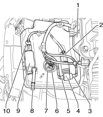
12.5. Washer fluid reservoir connections 1. Washer fluid reservoir; 2. Pump connector 4; 3. Connection of the washer fluid supply hose to the rear window, with a white mark; 4. Windscreen washer fluid supply pump; 5. Windshield washer fluid supply hose connection, with black mark; 6. Sensor connector 7; 7. Low washer fluid level sensor; 8. Connection of the washer fluid supply to the headlights; 9. Headlight washer fluid supply pump; 10. Pump connector 9
6. Remove from the filler neck (2 in the illustration) eVAP system tube (3) or auxiliary heater tube and unscrew the screw (1). Remove the headlight (see Section 5).
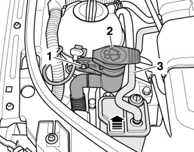
12.6. Removing the tank neck
Note: When installing, tighten the screw to 8 Nm.
7. On models without additional heating, unscrew the bolts and nuts (see illustration) and remove the tank downwards.
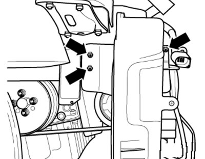
2.7. Tank fastening (models without additional heating)
Note: When installing, tighten the fasteners to 8 Nm.
8. On models with additional heating, remove the front bolts on the side and the lower bolts on the top, gently push the tank forward, release it from its support in the bracket and remove it downwards.
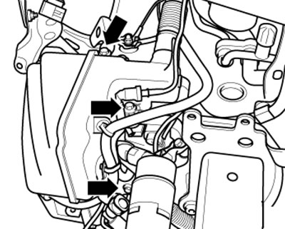
12.8. Tank fastening (models with additional heater)
Note: When installing, tighten the side bolts to 8 Nm and the bottom bolt to 5 Nm.