



Contents: Side light/instrument light switch…⬇ Headlight low beam switch (2) ⬇ Rear window defroster switch (3) ⬇ Front fog light switch (4) ⬇ Rear fog light switch (5) ⬇ Hazard warning switch (6) ⬇ Front seat heating switches (7, 8) ⬇ Left combination steering column…⬇ Right combination steering column…⬇ Windscreen wipers ⬇ Windscreen washers ⬇ Headlight lens washers ⬇ Rear door glass cleaner and washer ⬇ Control Panel ⬇ General instructions ⬇
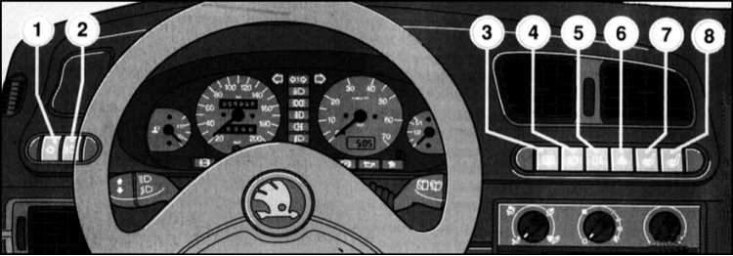
The location of the instrument panel and steering column switches is shown in the illustration.
Note: The numbering given in the text corresponds to the given illustration.
On right-hand drive models, the switch arrangement is slightly different from that described in this subsection. However, all symbols remain the same.
Remember that the use of lighting and signaling devices must be carried out in accordance with traffic regulations and federal laws.
When opening any of the front doors of the car, a special signal buzzer will warn the driver of the need to turn off the external lights. The buzzer functions even when the ignition is off. To turn off the buzzer, just slam both front doors, which allows you to park the car with the side lights on if necessary.
Side light/instrument light switch (1)
 This switch is used to turn on the vehicle's side lights and instrument panel/control lighting.
Headlight low beam switch (2)
 Activation of the low beam headlights can only be performed when the parking lights are on. After the ignition is turned off, the headlights are switched off automatically.
Rear window defroster switch (3)
 The rear heater only functions when the ignition is on. The heater's heating element consumes a lot of electricity, so to avoid draining the battery, the heater should be turned off as soon as the glass becomes sufficiently transparent.
Note: On models equipped with an electrical package, the heated outside rearview mirrors are also turned on at the same time as the heated rear window.
Front fog light switch (4)
 Activation of the fog lights is only possible when the parking lights and low/high beam headlights are on.
Rear fog light switch (5)
 Activation of the rear fog lights is also possible only after switching on the low/high beam headlights, or only after switching on the front fog lights (depending on the model and region of vehicle operation).
Note: The factory-fitted towbar electrical connector is designed so that when the trailer fog light is turned on, the vehicle's rear fog lights are automatically turned off.
Hazard warning switch (6)
 When the hazard warning lights are switched on, all of the vehicle's turn signals and their indicator lights are activated simultaneously.
Front seat heating switches (7, 8)
 When the ignition is on, it is possible to heat the front seats of the car. The heating element of the driver's seat heater is activated using button (7), and button (8) turns on the heating of the passenger seat.
The seat heating switches off automatically after approximately 4 minutes.
Note: To avoid draining the battery, the authors of this Manual recommend that you only use seat heating when the engine is running.
On right-hand drive models, the switches are located in a mirror image of the order shown in the illustration.
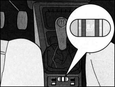
On some models, the front seat heating switches are located on the center console behind the manual transmission control lever, between the power window controls.
Switch for adjusting the position of the optical axis of the headlights
 .
.
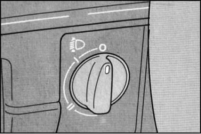
The switch is located in the lower left corner of the vehicle's instrument panel between the air duct deflector and the steering column. By rotating the control handle, the direction of the optical axis of the headlights can be smoothly adjusted in accordance with changes in the vehicle's load level.
The zero position of the switch is the basic one. Correct adjustment of the tilt of the optical axis of the headlights allows achieving the best illumination of the road with a minimum risk of blinding drivers of oncoming and passing vehicles. Below is a table of the correspondence of the switch positions to various degrees of vehicle loading.
| Position of the switch handle | Vehicle loading level | |
Station wagon | Pickup | |
| 0 | 1÷2 persons, without cargo | 1÷2 persons, without cargo |
| I | 5 people + 75 kg of cargo | 1÷2 persons + 350 kg of cargo |
| II | 1 person at full load | 1 person + 450 kg of cargo |
Note: On Pickup models with a specialized body, when the vehicle is already unloaded, the control handle should be set to a position between 0 and I.
Left combination steering column switch

This switch controls the operation of the direction indicators and switches the operating modes of the headlights.
The direction indicators can only be activated when the ignition is on. To turn on the right-hand turn indicators, move the switch lever to the upper position (until it clicks). To turn on the left-hand turn indicators, lower the lever to the lower position. The correct operation of the indicators is confirmed by the indicator lamps built into the instrument cluster (see above). The indicators are switched off automatically when the steering wheel is returned to the straight-ahead position. If there is a need to briefly turn on the indicators (for example, when overtaking or changing lanes), you only need to press the switch lever slightly in the appropriate direction (without a click) and manually hold it in this position for the required time.
The high beam headlights can only be switched on after the low beam has been activated and is done by pressing the steering column switch lever until it clicks towards the instrument panel. A control lamp is mounted in the instrument cluster, emitting a blue glow, confirming that the high beam is on (see above). The high beam is switched off by returning the lever to its original position. It is possible to warn other road users by flashing the high beam headlights (regardless of whether the low beam is on or not). Pull the steering column switch lever towards you - the high beam is turned on, which is confirmed by the control lamp. In this position, the lever is sprung and automatically returns to its original position when released.
Note: The use of high beam headlights must be carried out in compliance with traffic regulations.
Right combination steering column switch
This switch activates the windshield wipers and washers. The windshield wipers/washers can only operate when the ignition is on. To avoid dangerous overloads of the drive motor circuit, before turning on the windshield wipers before driving in frosty weather, make sure that the brushes are not frozen to the glass surface.
Windscreen wipers
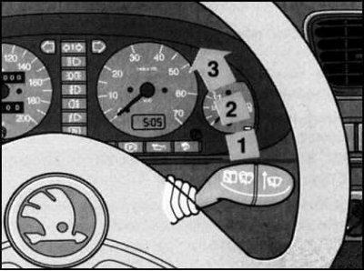
To operate the windshield wipers once, press the lever slightly to the position preceding position 1.
The interval mode of operation of the windshield wipers is activated by moving the lever to position 1. The basic period of operation of the brushes is 4 seconds, but it is possible to adjust it in the range from 2 to 35 seconds.
After turning on the interval mode of the windshield wipers, wipe the glass once, then turn off the brushes. Wait for a pause, the duration of which is equal to the set period of operation of the windshield wipers, then turn on the interval mode again.
The slow wiper mode is activated by moving the steering column switch lever to position 2.
Position 3 of the lever corresponds to the high-speed mode of operation of the brushes.
Windscreen washers
To wash the windshield, pull the right steering column switch towards you. The wiper blades are turned on at the same time. After releasing the lever, the supply of fluid to the glass stops, and the wipers turn off automatically after one to three more cycles.
Headlight lens washers
The headlight lens washers are automatically activated when the windshield is washed.
From time to time, sticky dirt and insect debris should be removed manually from the lens surfaces. The easiest way to do this is to add it to refueling the car. In the cold season, monitor the patency of the washer nozzles, periodically cleaning them from snow and ice accumulations (use special defrosting aerosols).
Rear door glass cleaner and washer
The rear window wiper is operated by pressing the switch lever to the first stop towards the instrument panel. The wiper will continue to operate as long as the lever is held pressed.
By pressing the lever even further, the windshield washer is also turned on.
When the lever is released, the windshield wiper and washer are switched off automatically.
If you hold the lever in the depressed position, after releasing it, the windshield wiper will operate two or three more times.
By pressing the lever momentarily, the interval mode of the windshield wiper is switched on. The period of operation of the brush in this mode is 5 seconds. The interval mode is switched off by pressing the switch lever again.
Equipment of the control panel and air duct deflectors, selection of operating modes of the interior heating/ventilation system - models without air conditioning.
Control Panel
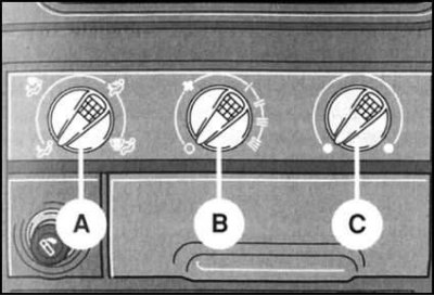
Air distribution direction handle (A)
This handle is used to select the direction of air distribution between the air ducts of the interior heating/ventilation system.
Fan speed/air intake shut-off mode selection knob (B)
This handle regulates the flow of air pumped into the cabin. The handle has five discrete positions (0, I, II, III and IIII). In position 0 of the handle, the fan is switched off and the air intake tract is completely blocked, which prevents heavily polluted or foul-smelling air from entering the passenger compartment. To avoid fogging of the windows and the creation of a stuffy atmosphere in the passenger compartment, do not block the air intake for a long time.
Handle for adjusting the temperature of the air supplied to the passenger compartment (C)
In the extreme left position the heater is switched off. Smooth increase of the temperature of the injected air is carried out by turning the handle clockwise.
Air duct deflectors
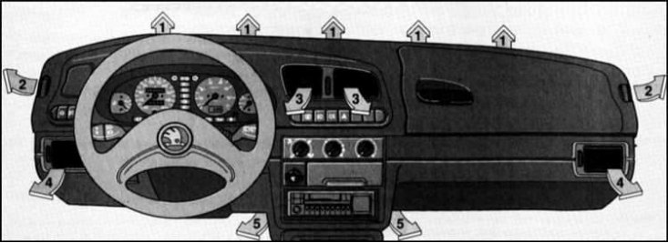
Depending on the selected position of the handle, cold or heated air is supplied from the control panel into the vehicle interior through the air duct deflectors. The distribution of air between the system air ducts is carried out using handle A. In addition, instrument panel deflectors 3 and 4 (see accompanying illustration) equipped with rotary louvers and a damper, allowing to change the direction of the outgoing flow, or to completely block the supply at the operator's discretion. The flow section of the deflector is blocked by turning the control wheel down. To open the supply, the wheel should be turned up. The deflector's louvered grille guide is turned using the control lever.
Air is supplied to the front and rear footwells through lower level air ducts 5, which are combined into a common tract.
Windshield and side window defrost mode when they are frozen
Turn the control panel handle B to position IIII. Turn the handles A and C all the way to the right. Close the flaps of the air vents 3. Turn the louvered grilles of the air vents 4 so that the air flows out in the direction of the front door windows of the vehicle.
Preventing fogging of windshield and side windows
At high air humidity (rain, fog, etc.) car windows tend to fog up.
To remove condensation, turn the control panel handle B to position II or III. In cold weather, turn on the heater by turning handle C to the required position. Move handle A to position
 . Close the air vents 3. Turn the louvered grilles of the air vents 4 so that the air flows out in the direction of the front door windows of the vehicle.
Accelerated heating of the passenger compartment
Turn the handle B of the control panel to position IIII, turn C all the way to the right. Turn the handle A to position
 . Close the air duct deflectors 3 and 4.
Creating comfortable temperature conditions in the car interior
After removing condensation from the glass and warming up the interior, make the following adjustments:
Turn handle B to position II or III. Move handle C to the position corresponding to the optimum temperature of the air supplied to the passenger compartment.
Set handle A to position
 and close the air duct deflectors 3. Turn the louvered grilles of the air duct deflectors 4 to the optimal position at your discretion.
Cabin ventilation mode
To ventilate the passenger compartment, it is necessary to ensure that outside air is supplied to it through air duct deflectors 3 and 4.
Using handle B, select the desired fan speed mode. Turn handle C all the way to the left. Move handle A to position
 , or
, or  , depending on the specific situation. Open the air supply through air duct deflectors 3 and 4.
General instructions
The correct functioning of the elephant's heating/ventilation system is possible only if the air intake grille located in front of the car's windshield is normally passable. Monitor the condition of the grille, clean it from time to time from snow, ice, stuck leaves and other debris.
All control panel handles, with the exception of handles A and B, allow smooth adjustment of the controlled parameters.
You can avoid fogging of the windows when the vehicle is moving slowly by selecting the maximum speed mode of the heater fan.
The performance of the heater heat exchanger directly depends on the temperature of the coolant. Maximum output can only be achieved after the engine has warmed up to normal operating temperature.
Air circulation in the passenger compartment is ensured by constant outflow through the ventilation openings located at the bottom of the rear doors of the car.