



Contents: Petrol models ⬇ Diesel models ⬇
Petrol models
1. The installation details of the fuel tank and its components are shown in the illustrations.
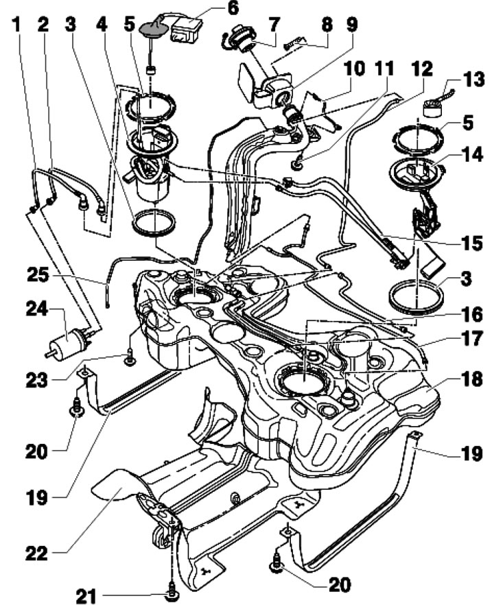
11.1a. Fuel tank installation details and its components (petrol models up to 06.2010.) 1. Fuel supply line, black; 2. Return fuel line, blue; 3. Sealing ring, subject to replacement, inserted dry, only the inner flange seal is lubricated with fuel (for installation); 4. Fuel supply module, with fuel reserve sensor "G"; 5. Retaining ring, 110 Nm; 6. Fuel pump control unit "J538", after replacement ECM adaptation is required; 7. Fuel tank cap; 8. Fixing screw; 9. Assembling the neck, with a rubber cup; 10. Body mass connection; 11. Bolt, 11 Nm; 12, 16, 17. Ventilation line; 13. Sensor wiring connector 14; 14. Sensor No. 2 "G169" fuel reserve; 15. Suction jet pump, fixed on the sensor body 14; 18. Fuel tank; 19. Clamp; 20. Bolt, 25 Nm, subject to replacement; 21. Bolt, 23 Nm; 22. Heat shield, riveted together with the exhaust pipe hanger; 23. Bolt, 3 Nm; 24. Fuel filter; 25. Ventilation line, attached to the side of the tank
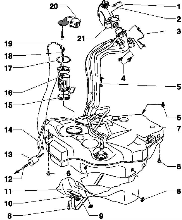
11.1b. Fuel tank installation details and its components (petrol models from 06.2010.) 1. Support part; 2. Fuel tank cap; 3. Body mass connection; 4. Bolt, 11 Nm; 5. Guide; 6. Bolt, 25 Nm, subject to replacement; 7. Fuel tank; 8. Retaining ring; 9. Bracket for the exhaust pipe; 10. Clamp; 11. Heat shield; 12. Fuel supply line, to the fuel distribution line; 13. Fuel filter; 14. Ventilation line, attached to the side of the tank; 15. Sealing ring, subject to replacement, inserted dry, only the inner flange seal is lubricated with fuel (for installation); 16. Fuel supply module, with fuel reserve sensor "G"; 17. Retaining ring, 110 Nm; 18. Fuel supply line, black, attaches to the side of the tank; 19. Return fuel line, blue, attaches to the side of the tank; 20. Fuel pump control unit "J538", after replacement ECM adaptation is required; 21. Assembling the neck, with a rubber cup
2. Empty the tank and disconnect the devices used for this purpose (see Section 3).
3. On models before 06.2010, remove the cover of sensor No. 2 "G169" and disconnect its connector (right arrow in the illustration).
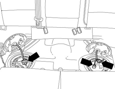
11.3. Fuel tank wiring connectors
4. Clean the filler neck and surrounding area, then seal it to prevent dirt from entering.
5. Remove the rear right wheel and rear right wheel arch liner. Unscrew the bolts (1 in the illustration) filler neck, unhook the electrical wiring from the bracket (2) at the top and bottom of the neck.
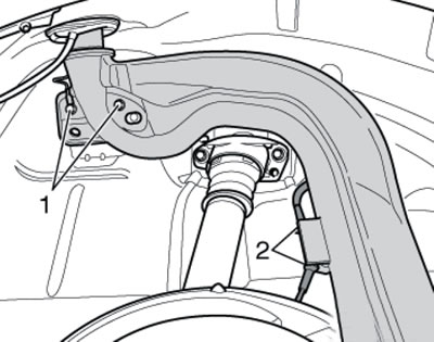
11.5. Neck fastening
6. Disconnect the white vent line (1 in the illustration) and the black supply line (2). On models with additional heater, additionally disconnect the supply line of the metering pump "V54". On models up to 06.2010, proceed to paragraph 8.
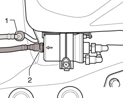
11.6. Connecting node
7. On models from 06.2010, remove the middle and rear mufflers (see Part B), unscrew the bolts (2 and 4 in the illustration) and remove the clamp. Support the tank with a transmission jack, remove the bolts (1 and 3) and lower the tank slightly. With the help of an assistant, remove the tank from the jack, passing the filler neck between the body and the rear suspension. To install, proceed to paragraph 10.
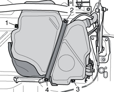
11.7. Fuel tank fastening from 06.2010.
8. Remove the rear cross member of the central tunnel (see illustration). Unhook the rear muffler from the two clamps, loosen the double clamp nuts and remove the rear exhaust pipe hanger bolts. Remove the rear muffler.
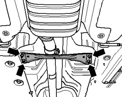
11.8. Rear tunnel cross member
9. Remove the bolts (2, 5 and 6 in the illustration), support the tank with a transmission jack, remove the bolts (1, 3, 4 and 7) and lower the tank a little. With the help of an assistant, remove the tank from the jack, passing the filler neck between the body and the rear suspension.
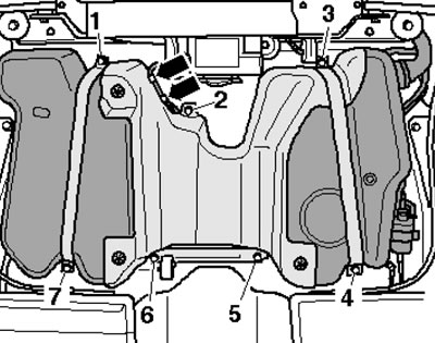
11.9. Fuel tank fastening before 06.2010.
10. Before installation, check and, if necessary, remove corrosion from both ground connections. Ground wire (1 in the illustration) must be firmly attached to the ring (2), the contact (4) must hang on the tank (3) and must be secured using the spacer sleeve (5).
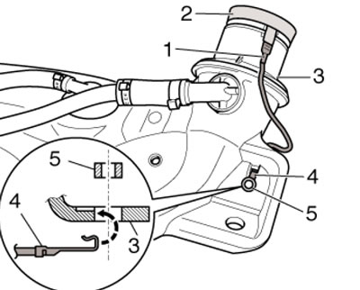
11.10. Ground connection on the tank
Article source: this website www.skodabook.ru
11. Installation is carried out in reverse order. Arrow (2 in illustration 3.18) on the lid should face forward.
Diesel models
12. The fuel tank installation details and its components are shown in the illustration.
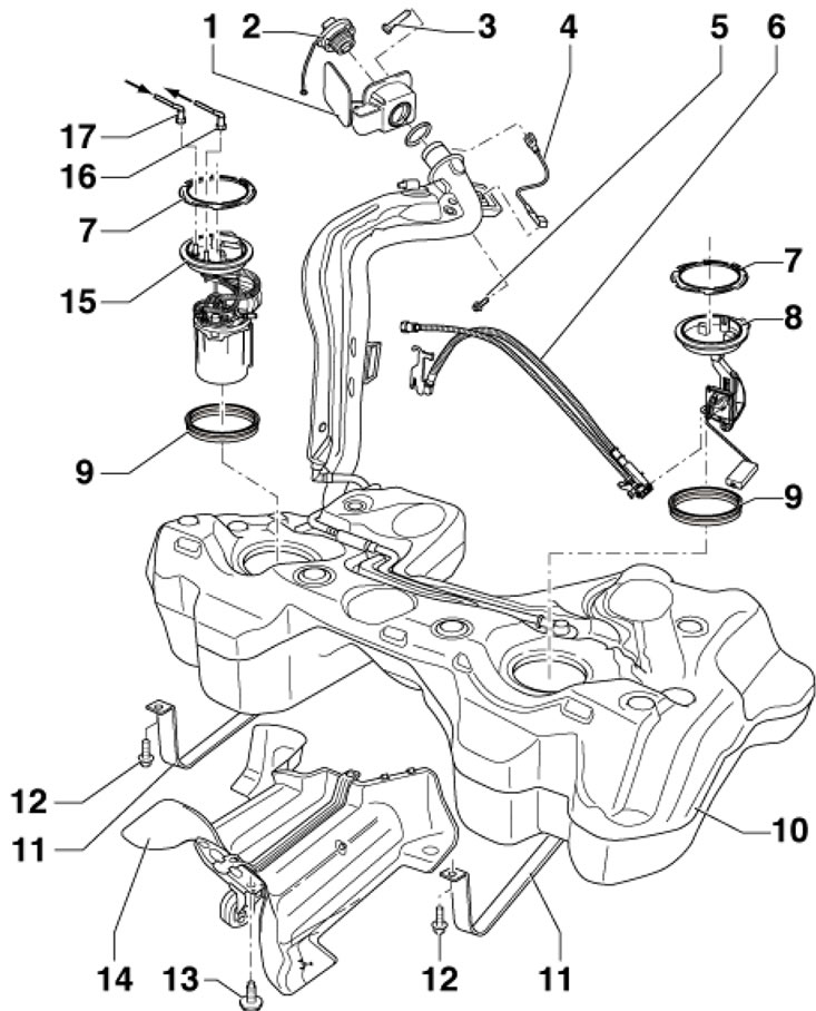
11.12. Fuel tank installation details and its components (diesel models) 1. Assembling the neck, with a rubber cup; 2. Fuel tank cap; 3. Support part; 4. Body mass connection; 5. Bolt, 10 Nm; 6. Jet pump; 7. Retaining ring, 110 Nm; 8. Sensor No. 2 "G169" fuel reserve; 9. Seal, subject to replacement; 10. Fuel tank; 11. Clamp; 12. Bolt, subject to replacement, 25 Nm; 13. Bolt, 25 Nm; 14. Heat shield; 15. Fuel supply module, with fuel reserve sensor "G"; 16. Fuel supply line, black, to fuel filter; 17. Return fuel line, blue, from fuel filter