



Contents: Engine 1.2 l ⬇ Engine 1.4 l ⬇ Petrol engines 1.8 l ⬇ Diesel engines 2.0 l (CFHC, CFJA and…⬇
Engine 1.2 l
1. The installation details of the intake manifold and throttle module are shown in the illustrations.
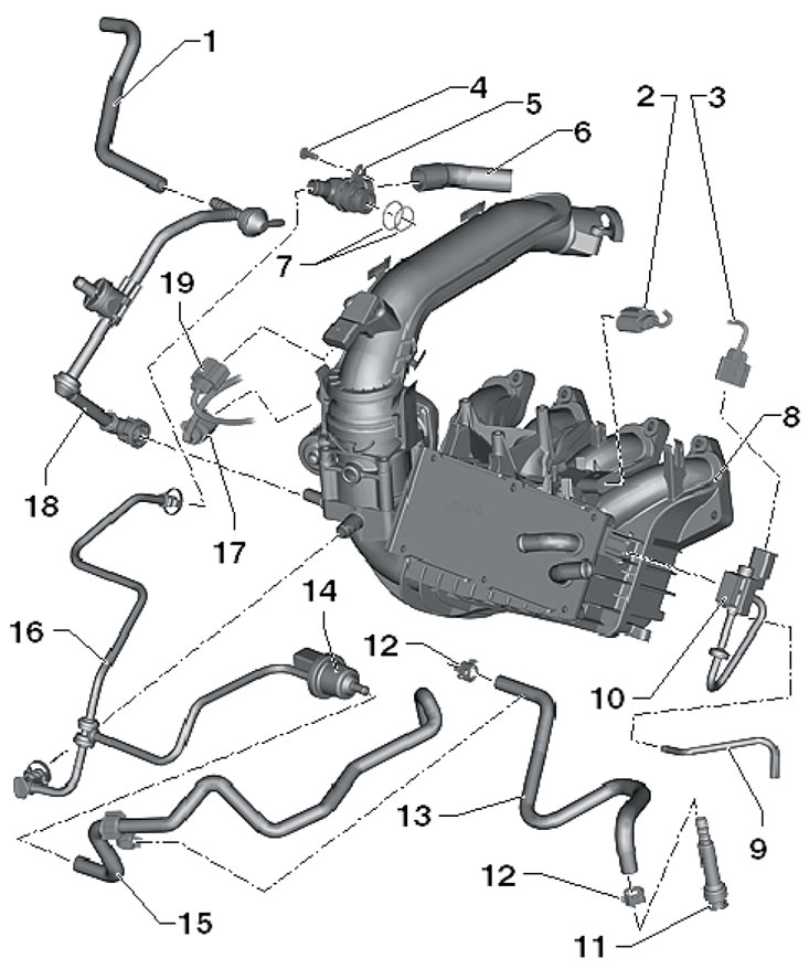
7.1a. 1.2L Engine Intake Manifold and Throttle Valve Installation Details, Part 1 of 2 1. Connecting hose, on the camshaft housing; 2. Connector of the "G71" sensor of pressure in the intake manifold; 3. Connector of electrical wiring of the electromagnetic valve of control of the coolant pump; 4. Bolt, 10 Nm; 5. PCV non-return valve; 6. Connecting hose to turbocharger; 7. Sealing rings are subject to replacement; 8. Intake manifold, with sensor G71 (when removing the sensor, its plastic retaining ring breaks and the sensor must be secured with bolts, tightening them to 3 Nm); 9. Connecting hose to coolant pump; 10. Solenoid valve "N492" of the coolant circuit; 11. Fuel supply connection; 12. Clamp; 13. Low pressure fuel hose to the high pressure fuel pump; 14. Solenoid valve No. 1 "N80" for purging the adsorber; 15. Connecting hose to the adsorber; 16, 18. Connecting hose; 17. Throttle body module connector "J338"; 19. Connector for boost pressure sensor "G31" combined with sensor "G299" IAT No. 2
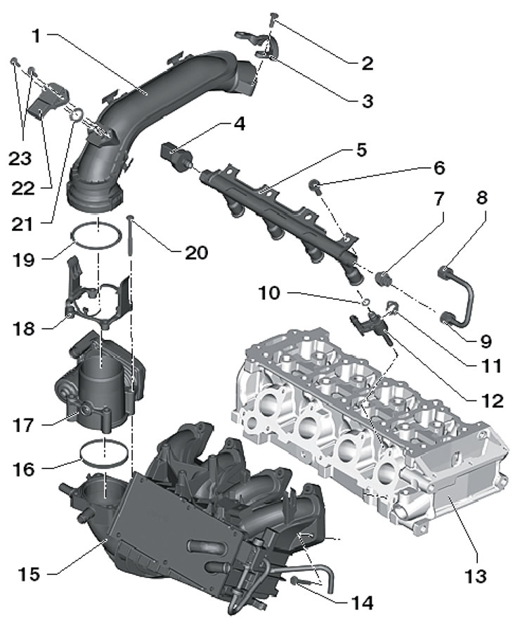
7.1b. 1.2L Engine Intake Manifold, Throttle Valve and Fuel Rail Installation Details, Part 2 of 2 1. Pressure tube; 2, 20. Bolt, 7 Nm; 3. Holder; 4. Sensor "G247" fuel pressure, 22 Nm; 5. Fuel distribution line; 6, 14. Bolt, 20 Nm; 7. Connection, 30 Nm; 8, 9. Union nuts, 25 Nm; 10. Sealing ring, subject to replacement; 11. Spring element; 12. Injector, with replaceable Teflon seal and support washer; 13. Cylinder head; 15. Intake manifold with sensor "G71" of pressure in the intake manifold; 16, 19, 21. Sealing ring, subject to replacement; 17. Throttle body module "J338"; 18. Adapter; 22. Boost pressure sensor "G31", combined with sensor "G299" IAT No. 2; 23. Bolt, 5 Nm
2. Turn off the ignition and all electrical appliances, remove the key from the ignition switch.
3. Remove the bolts (1 in illustration 9.16 Chapter 2) and remove the holder. Disconnect the connector (2) of the boost pressure sensor "G31", combined with the IAT sensor No. 2 "G299". Press the clamps in the direction of the arrows and pull the pressure air tube (3) first from the throttle module "J338", and then from the turbocharger.
4. Disconnect the connector (1 in the illustration) module "J338" of the throttle valve, unscrew the bolts (2) and remove the module from the intake manifold. If necessary, after removing the throttle module, remove the intake manifold as described below.
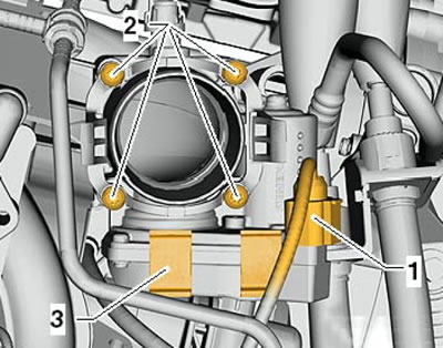
7.4. Connector and fastening of the throttle module
5. Disconnect the fuel supply hose (1 in the illustration) and disconnect the connector of the solenoid valve No. 1 "N80" of the EVAP adsorber, remove the valve from the intake manifold. Disconnect the connectors (1 and 4), unscrew the bolts (7) and carefully place the ignition module "N152" (6) on the cylinder head cover. Disconnect the connecting hose (5) from the intake manifold and the vacuum line of the solenoid valve of the coolant circuit "N492" (2) from the coolant pump. Clamp the coolant hoses, loosen the clamps (3) and disconnect the coolant hoses from the intercooler.
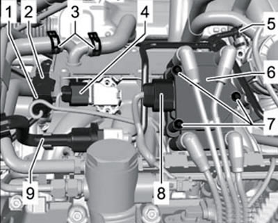
7.5. Inlet manifold connections
6. Remove the bolts (1 in the illustration) diagonally and carefully remove the intake manifold upwards together with the intercooler. Drain the remaining coolant from the intercooler. If necessary, remove the intercooler (see Section 6).

7.6. Fastening the intake manifold
7. Installation of the intake manifold is carried out in the reverse order. Tighten the intake manifold mounting bolts to 20 Nm. Finally, fill and bleed the engine cooling system (see Chapter 3). When installing the throttle module, pay attention to the following points.
8. Install the new throttle module into the groove in the intake manifold. If necessary, clean the throttle module as described in paragraphs 9-10.
Note: If a new ECM is installed, the throttle module must be adjusted. Adaptation is only allowed for a new or cleaned old module, since deposits and carbon deposits in the extreme position can lead to incorrect adaptation values. Be careful not to scratch the throttle module when cleaning.
9. Open the removed throttle valve by hand and fix it in the open position using a wooden or plastic wedge (see illustration), so as not to scratch it.
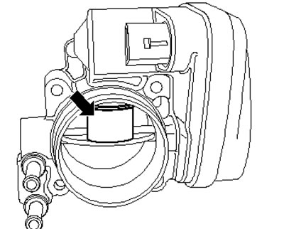
7.9. Fixing the damper in the open position
10. Clean the throttle module thoroughly with acetone (according to DIN 53247) and brushes, paying special attention to the cylindrical surface mating with the valve.
Caution: Acetone is extremely flammable. When cleaning, do not use compressed air, wear protective glasses and gloves. Wipe the throttle body with a lint-free cloth and allow the acetone to evaporate completely.
11. Position the throttle module with the adapter on the intake manifold and tighten the module mounting bolts to 7 Nm. Connect the module wiring connector.
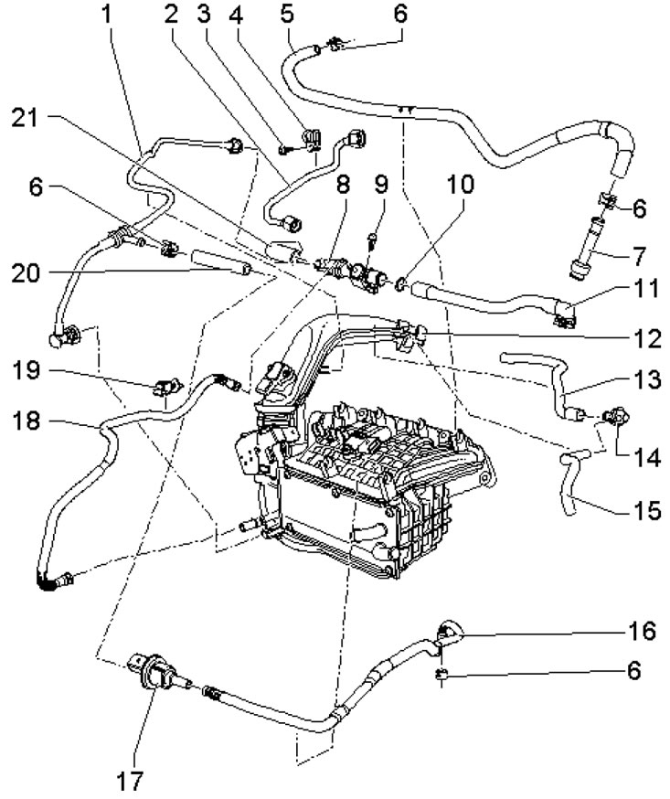
7.11a. Intake manifold connections 1, 18, 20. Connecting hose; 2. High pressure fuel pipe, 18 Nm (on the high pressure fuel pump) and 20 Nm (on the bottom of the intake manifold); 3, 9. Bolt, 8 Nm; 4, 19. Holder; 5. Low pressure fuel hose to the high pressure fuel pump; 6. Spring clamp; 7. Connection for fuel supply line; 8. PCV non-return valve; 10. Sealing ring; 11. Connection, on the timing case; 12. Pressure pipe, from turbocharger; 13. Connecting hose, on the timing case; 14. Non-return valve; 15. Connecting hose, on the air cleaner; 16. Connecting hose, on EVAP canister; 17. Solenoid valve No. 1 "N80" EVAP; 21. Connecting hose, on turbocharger
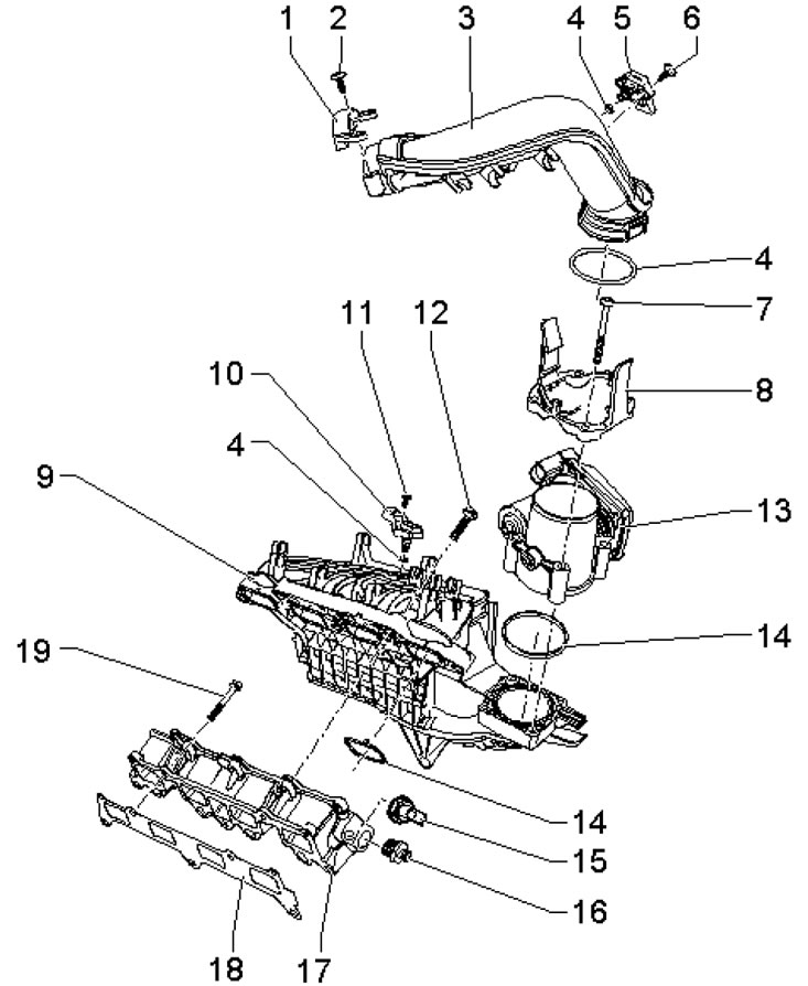
7.11b. Intake manifold installation details (1.4 l engines, except SAKHA) 1. Holder; 2, 7. Bolt, 7 Nm; 3. Pressure tube; 4, 14. Sealing ring, subject to replacement; 5. Boost pressure sensor "G31" with IAT sensor No. 2 "G299"; 6, 11. Bolt, 5 Nm; 8. Adapter; 9. Upper part of the intake manifold, with intercooler; 10. Sensor "G71" of pressure in the intake manifold; 12, 19. Bolt, 20 Nm; 13. Throttle module "J338", after replacement ECM adaptation is required; 15. Fuel pressure sensor "G247", 22 Nm; 16. 80 Nm; 17. Lower part of the intake manifold; 18. Gasket, subject to replacement
9. Lubricate the O-rings on the turbocharger and pressure pipe with engine oil, install the pressure pipe onto the turbocharger, and then onto the throttle module. The tube should be fixed in the clamps with an audible click. Tighten the pressure pipe bolts and connect the combination sensor connector.
10. If a new throttle module or a new ECM is installed, the adapted values must be cleared and the ECM must be adapted to the throttle module again using a scan tool (see Chapter 5). Adaptation can only be carried out with a new or cleaned throttle module, as deposits at the end of the throttle travel can lead to incorrect adaptation values.
Engine 1.4 l
11. The installation details of the intake manifold are shown in the illustrations. Removal of the upper part of the intake manifold is possible only after removal of the throttle module, and removal of the lower part of the intake manifold is possible only after removal of its upper part. The actions are similar to those on the 1.2L engine (see above).
Petrol engines 1.8 l
12. The installation details of the intake manifold are shown in the illustration. To remove only the throttle valve, follow the steps in paragraphs 13-15. The intake manifold is removed together with the fuel rail (paragraphs 16-32), after which they can be separated from each other (paragraphs 33-34).
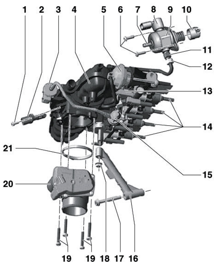
7.12. Intake manifold installation details (1.8L engines) 1. Sensor bolt 2.5 Nm; 2. IAT sensor "G42"; 3. Solenoid valve No. 1 "N80" EVAP, with valve 15; 4. Inlet manifold; 5. Vacuum block (installation element) for intake manifold flap valve; 6. Fuel injection pump bolts, subject to replacement, 10 Nm; 7. Fuel line connector from the fuel tank; 8. Valve "N276" fuel pressure regulation; 9. Fuel injection pump, with valve 8; 10. Roller pusher; 11. High pressure fuel line connection, to be replaced, 22 Nm; 12. Fuel pipe to fuel distribution line, 18 Nm; 13. Control valve "N316" of the intake manifold flap; 14. Injectors, sealing and Teflon rings are subject to replacement; 15. Double non-return valve, built into valve 3; 16. Intake manifold support; 17. Support bolt 16, 23 Nm; 18. Support nut 16, 10 Nm; 19. Module bolts 20, 4 pcs., 5 Nm; 20. Throttle body module "J338", ECM adaptation required when replacing; 21. Seal, subject to replacement
13. Loosen the clamp (2 in illustration 23.16 Chapter 2), unscrew the bolt (4) and disconnect the connector (arrow).
14. Remove the sound insulation under the engine compartment (see chapter 11), loosen the clamps (1 and 2 in Illustration 2.10 Chapter 3) and remove the air pressure hose. Remove the bolt (1 in illustration 23.16 Chapter 2) and remove the air pressure tube downwards.
15. Disconnect the connector (1 in illustration 4.23 Chapter 3), unscrew the bolts (arrows) and remove the throttle module. Cleaning the throttle module is done in the same way as on the 1.2L engine (see above). For installation, go to paragraph 35.
16. Remove the air cleaner (see Section 4).
17. Clean the connection between the intake manifold and the cylinder head.
18. Disconnect the vacuum line (arrow on the illustration), going to the EVAP canister, and also disconnect the connectors of the following parts: IAT sensor "G42" (1), throttle valve module "J338" (2), solenoid valve No. 1 "N80" EVAP and CMP sensor "G40".
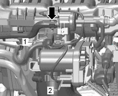
7.18. Connections
19. Disconnect the vacuum line (1 in the illustration) at the connection point (2) and remove the PCV hose (3).
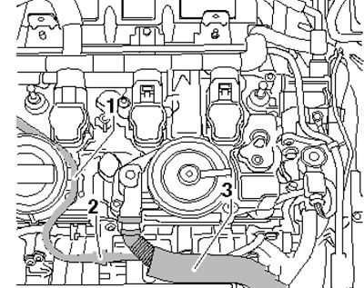
7.19. Vacuum line (1) and PCV hose (3)
20. Remove the bolts (see illustration) fuel supply pipe and set it aside.
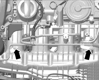
7.20. Fuel supply pipe bolts
21. Relieve the fuel pressure (see Section 3) and remove the union nut of the fuel line to the high-pressure fuel pump (bottom arrow in the illustration).
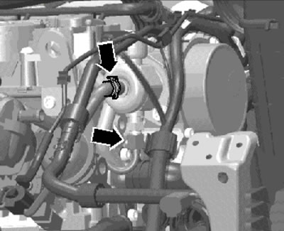
7.21. Fuel pipes
22. Disconnect the vacuum tube (see illustration) from the valve "N316" of the intake manifold flap.
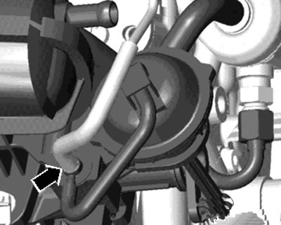
7.22. Vacuum tube on valve N316
23. Remove the coolant pipe mounting bolts from the intake manifold (see illustration 30.34 Chapter 2).
24. Disconnect the connector (1 in illustration 30.23) fuel pressure sensor "G247".
25. Perform the actions described in paragraphs 13-14.
26. Disconnect the connectors (1-3 in the illustration) and unscrew the holder from the intake manifold.
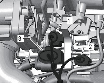
7.26. Electrical wiring connectors
27. Give the nut (1 in illustration 30.25 Chapter 2), unscrew the bolt (2) and remove the intake manifold support.
28. Unscrew the oil filter with wrench No. 3417 and cover the oil filter holder to prevent dirt from getting into it.
29. Loosen the electrical wiring holders (see illustration).
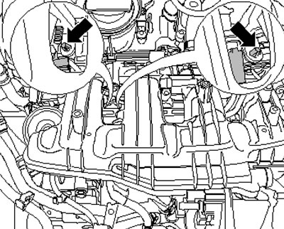
7.29. Wiring Holder
30. Release the cable from the intake manifold (see illustration).
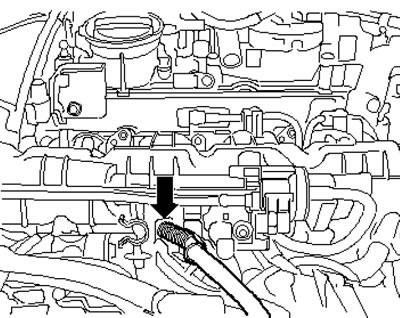
7.30. Cables on the intake manifold
31. Give me the nuts (And in the illustration) and loosen the bolts (arrows) of the intake manifold. Carefully pull the intake manifold and fuel rail slightly out of the cylinder head.
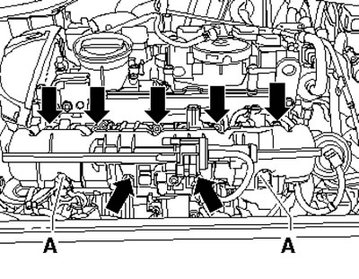
7.31. Fastening the intake manifold
32. Disconnect the connector (see illustration) sensor "G336" of the intake manifold flap position and remove the intake manifold. Plug the inlet ports with a clean cloth.
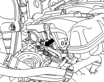
7.32. Sensor connector G336
Note: Injectors may remain in the fuel rail.
33. Pull the solenoid valve No. 1 "N80" EVAP out of the holder (arrow on the illustration). Remove the double non-return valve (1) and fuel pipe (2).
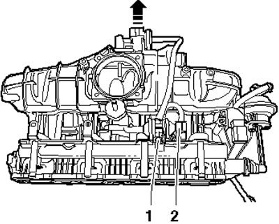
7.33. Solenoid valve N80 and double non-return valve
34. Loosen the clamp (1 in the illustration) hose, unscrew both lower bolts (arrows) and pull the fuel distribution line out of the intake manifold.
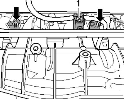
7.34. Fuel distribution line bolts
35. Installation is carried out in reverse order. Please note the following features.
36. Before installing the intake manifold and fuel rail assembly, the injectors must be installed in the cylinder head. If the intake manifold was pulled out slightly again during installation and the injectors remained in the fuel rail, they must be reinstalled in the cylinder head.
37. If a new module "J338" is installed, clear the adapted values and re-adapt the ECM to this module using the diagnostic tool. After installing a new intake manifold, the throttle position sensor "G336" must be adapted to the ECM.
Diesel engines 2.0 l (CFHC, CFJA and CLCB)
38. The details of the installation of the intake manifold are shown in the illustration.
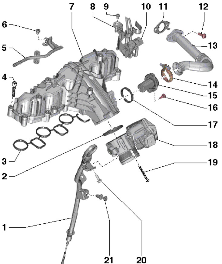
7.38. Installation details of the intake manifold of 2.0 l engines (CFHC, CFJA and CLCB) 1. Engine oil dipstick guide tube; 2.17. Sealing ring, subject to replacement; 3.11. Gasket, subject to replacement; 4, 16, 19. Bolt, 8 Nm; 5. Return fuel line; 6.9, 20. Bolt, 9 Nm; 7. Inlet manifold; 8. Valve bracket 10; 10. Switching valve "N345" of the EGR cooler; 12. Bolt, 20 Nm; 13. EGR radiator connecting pipe; 14. Clamp, 5 Nm, subject to replacement; 15. EGR connection; 18. Throttle module "J338", with potentiometer "G69"; 21. Tube retainer 1